
By CustomMotorDesign Engineering Team
Axial Flux Motor Rotor Disc Stress Calculator
Screen stress and retention loads. Assembly strength requires verification.
Stress & load worksheet
Instant screening for one isotropic disc and one magnet face. Replace illustrative defaults with project data.
80–600 mm
500–35000 rpm
2–35 mm
0–1.5 T
Preliminary loads — assembly strength unverified
Bare-disc stresses exclude attached magnets, hub fits, pockets and thermal effects. Retention values are demands, with no allowable or safety factor. Next: compare with a model of the actual assembly and qualified material/joint data.
Edit geometry, material & clearance assumptions
25–350 mm
1–2 ×
1000–20000 kg/m³
10–450 GPa
0.1–0.45
1–120 mm
1–18 mm
1000–20000 kg/m³
4–64 sectors; even whole numbers
0.1–0.95 ratio
0.3–3.5 mm
0.01–3 mm
No force cancellation applied. For DSSR evaluate each face and their difference separately.
Leave blank if unknown. Use measured/FEA mechanical stiffness at the rim under this load distribution and support condition, excluding magnetic feedback.
Mass, bending demand & retention details
- Disc + one-face magnet mass
- 2.599 + 0.761 kg
- Partial rotor inertia (excludes other hardware)
- 280.36 kg·cm²
- Rated tip speed / overspeed
- 113.1 m/s / 10800 rpm
- Normal pressure / assumed loaded area
- 336.8 kPa / 0.0184 m²
- Isotropic plate rigidity D
- 9846.2 N·m
- Required effective rim stiffness, F / allocation
- 34495 N/mm
- One-way rim displacement, F / supplied stiffness
- Unknown — supply mechanical stiffness
- Gap minus one-way displacement only
- Unknown — no operating gap prediction
- Nominal full-face bond shear demand, overspeed
- 6.23 MPa
Displacement uses a fixed magnetic load; runout, thermal growth, bearing motion and magnetic feedback are excluded. The displacement allocation is a user choice, not a standard. Bond shear assumes the full magnet face is bonded and omits peel and fatigue. A positive residual is not an operating clearance approval.
Free radial boundaries: σr = 0 at bore and rim; peak radial stress 20.8 MPa. Uniform, elastic, isotropic thin disc only. Thick sections, laminates, fits and cutouts need a different model.
1. Decision summary: screen loads, then verify the assembly
Axial flux motor rotor disc stress assessment needs separate centrifugal, magnetic bending and magnet-retention load cases. The worksheet answers a bounded first question: what self-stress and applied loads should the detailed assembly model address? A low bare-disc stress does not establish a safe rotor.
| Decision | What this page establishes | Evidence still needed |
|---|---|---|
| Rotation | Bare-disc radial and hoop stress at rated and user-selected overspeed | Hub fit, magnet loads, notches and hot material strength |
| Magnetic bending | Single-face pull, isotropic plate rigidity and required rim stiffness | Real support, field distribution, coupled displacement and both bending faces |
| Retention | Per-magnet centrifugal demand and nominal full-face bond shear demand | Qualified bond, pocket, sleeve or bolted-ring capacity |
| Clearance | One-way displacement if mechanical stiffness is supplied | Runout, tilt, thermal growth, bearing motion and magnetic stability |
The calculations and examples are conceptual engineering screens, not measured product performance, drawing release, prototype approval or aviation qualification. For architecture context, see special motor topologies. The evidence and method below identifies the model boundaries.
2. Inputs and evidence ownership
The default 240 mm disc, 70 mm bore and 8 mm thickness use illustrative isotropic steel properties: density 7,850 kg/m³, elastic modulus 210 GPa and Poisson ratio 0.30. These are editable assumptions, not a certified material grade. Magnet density defaults to 7,500 kg/m³. No yield strength or temperature derating curve is invented.
| Input group | Required detail | Owner / recovery if unknown |
|---|---|---|
| Geometry and topology | Disc bore, outside diameter, uniform thickness, SSDR/SSSR/DSSR arrangement | OEM assembly drawing; identify unknowns in the inquiry |
| Material | Density, modulus, Poisson ratio at the assessed condition | Material supplier; obtain grade, form, heat treatment and temperature data |
| Magnetic face | Normal flux, radial extent, circumferential coverage and actual load map | Electromagnetic analyst; worksheet uses uniform flux only |
| Magnets | Equal sector count, thickness, density and radial width | Magnet drawing; fixed 2 mm rim margin is a worksheet assumption |
| Support and clearance | Supported hub, bearings, mechanical rim stiffness and bending allocation | Structural analyst / test team; leave stiffness blank if unavailable |
| Manufacturing and tests | Pockets, bondline, fits, coatings, inspection and duty history | Manufacturing and validation team; agree a project evidence plan |
All numeric fields have visible bounds. Inconsistent geometry suppresses results and offers a reset. These are worksheet input bounds, not approved manufacturing ranges. A separate magnetic back-iron ring, hub, sleeve and fasteners are excluded from the partial mass and inertia; add them in the assembly model.
3. Centrifugal stress: what the free annulus represents
Conceptual workflow, not simulation or measured performance. Magnet and hub-fit loads are separate assembly load cases.
The worksheet uses linear elastic plane stress for a uniform isotropic annulus with traction-free bore and rim. It excludes fit pressure, attached magnets, torque transmission, temperature gradients and geometric discontinuities. With radii a, b, evaluation radius r in metres and ω = 2πN/60:
C = (3 + ν) ρ ω² / 8
σr(r) = C [a² + b² − a²b²/r² − r²]
σθ(r) = C [a² + b² + a²b²/r² − (1 + 3ν)r²/(3 + ν)]
At either free radial edge, σr = 0. The chart evaluates these equations at 81 radii; its curves are computed values, not an illustrative stress contour. The baseline gives 84.33 MPa bare-disc bore hoop stress and 20.78 MPa peak radial stress. The thin-disc idealization and its relation to three-dimensional elasticity are discussed by Lubarda & Lubarda, 2025. Thick sections or nonuniform carriers need a suitable structural model.
Adding magnet force as a fictitious uniform rim traction is not done here: the real bond/pocket contact location determines the load path. Likewise, a small-hole limit can approach twice the solid-disc center stress in this idealization; that is not a universal factor for every bore or fitted hub.
4. Overspeed and magnet centrifugal demand
At fixed geometry, elastic self-stress and centrifugal load scale with N². A user-selected multiplier of 1.2 raises these values by 44%; it is not a prescribed test requirement.
Conceptual workflow, not simulation or measured performance. The worksheet computes demand only. A retention mechanism name is not a strength rating.
For magnet annulus radii r1 and r2, total coverage c, magnet thickness tm, density ρm and equal sector count P:
A = π(r2² − r1²)c
Mmag = A tm ρm
Fmag,bound = (Mmag/P) r2 ω²
τnominal = Fmag,bound / (A/P)
J = 0.5 Mdisc(a² + b²) + 0.5 Mmag(r1² + r2²)
The force uses the outer magnet radius for all its mass, an upper bound on the sum of centrifugal force magnitudes for the assumed geometry. It is not the net vector force of the symmetric rotor. τnominal assumes the full sector face is bonded and does not model peel. Inertia is the exact axial polar inertia for these uniform annuli/sectors; 1 kg·m² = 10,000 kg·cm².
5. Magnetic bending: load before displacement
Conceptual workflow, not simulation or measured performance. Plate rigidity alone does not determine rim deflection; support and load distribution matter.
For an assumed uniform field normal to an air-gap face, the worksheet estimates traction magnitude p = Bn²/(2μ0) and force F = pA. Here μ0 ≈ 4π × 10⁻⁷ H/m. If a peak flux value is entered, treating it as uniform is a peak-field envelope over the assumed area, not a spatially averaged force prediction. Fringing, tangential field, slotting and saturation require the actual field solution. COMSOL's force-calculation documentation describes obtaining force by integrating Maxwell stress.
The default 0.92 T field and 0.018437 m² loaded area give 336.77 kPa and 6.209 kN on one face. A symmetric SSDR assembly may balance overall shaft thrust while each disc bends toward the central stator. For DSSR, evaluate both faces and their spatial pressure difference; no assumed 20% imbalance is applied. Both magnet faces must also enter the detailed mass and centrifugal model.
6. Rigidity, stiffness and clearance are different quantities
Isotropic plate rigidity is D = Et³/[12(1−ν²)], in N·m. It describes bending resistance but does not determine rim displacement without support geometry and load distribution. The page therefore reports required effective rim stiffness krequired = F / wallocated instead of an unsupported annular-plate deflection formula.
| Quantity | Baseline | Interpretation |
|---|---|---|
| Nominal face gap | 0.900 mm | User input before motion |
| Bending displacement allocation | 0.180 mm | Illustrative user allocation, not a standard |
| Required effective rim stiffness | 34,495 N/mm | For the assumed 6.209 kN load and allocation |
| Actual rim stiffness | Unknown by default | Obtain from the actual mechanical load case |
| Optional one-way displacement | F / ksupplied | Only for matching load distribution and supports |
| Operating minimum gap | Unverified | Requires complete tolerance and motion budget |
Conceptual workflow, not simulation or measured performance. An inverse-square force law and a one-third-gap limit are not universal permanent-magnet motor rules.
If supplied stiffness were 50,000 N/mm, the fixed-load displacement would be 0.124 mm, leaving 0.776 mm before other closures. That does not demonstrate stability or acceptable running clearance. The tool preserves negative residuals as an overlap warning. Magnetic force must be recalculated at displaced gaps for coupled analysis; a universal inverse-square force law or one-third-gap collapse threshold is not assumed for a permanent-magnet motor.
Discuss your support and clearance assumptions →
Continue with the air-gap allocation worksheet, stator cooling review or manufacturing feasibility screen when those decisions are also unresolved.
7. Retention alternatives: capacity requires geometry and tests
| Approach | Potential value | Cost / failure tradeoff | Minimum evidence |
|---|---|---|---|
| Adhesive bond | Low added mass and simple face placement | Surface preparation, cure control, peel and environmental aging | Representative joint strength and fatigue at service conditions |
| Machined pockets | Direct radial contact load path | Machining time, lip bending, brittle magnet contact and corner notches | Actual pocket/contact geometry and local stress model |
| Composite sleeve | Peripheral containment with tailored hoop stiffness | Tooling, layup, assembly interference and cold/hot contact | Orthotropic ply data, fit tolerances and failure analysis |
| Bolted ring | Inspectable mechanical retention | Added inertia, preload loss, fastener fatigue and ring deformation | Joint load distribution, preload and fatigue verification |
No universal rim-speed limit or allowable is assigned to these methods. ASTM D1002-10(2019) describes an apparent single-lap shear test; its published scope warns against transferring specimen strength directly to different structural joints. The worksheet's baseline overspeed nominal bond demand of 6.23 MPa is therefore a demand to investigate, not a retention pass.
Conceptual workflow, not simulation or measured performance. An isotropic metal yield calculation cannot qualify a CFRP sleeve.
8. Material, thermal and hub-interface tradeoffs
| Candidate | Structural decision | Magnetic / manufacturing boundary |
|---|---|---|
| Steel carrier / back iron | Use certified temperature-dependent strength and stiffness | Check magnetic properties, losses, corrosion and machining |
| Aluminum carrier | Lower density may reduce inertia | Separate return path adds mass and joints; thermal mismatch needs analysis |
| Titanium carrier | Evaluate specific strength and machining cost | Not a ferromagnetic return path; conductive and still subject to eddy-current heating |
| CFRP carrier or sleeve | Requires laminate stiffness and directional failure criteria | Excluded from the isotropic worksheet; contact and delamination matter |
| Lamination stack | Characterize joined stack behavior | Do not substitute solid-steel isotropic properties without evidence |
Conceptual workflow, not simulation or measured performance. No universal thermal derating coefficient or stress increment is assumed.
Cold/hot fits require temperature fields and expansion data for every contacting material, including magnets and adhesive. No fixed percentage increase in sleeve stress is assumed. Keyways introduce local features, while interference fits impose bore hoop stress and contact edge effects. Select the hub interface from torque, fatigue, assembly and service requirements; removing a keyway does not eliminate all stress concentration or fretting risk.
9. Three reproducible conceptual comparisons
Each preset uses the inputs in section 2, a 1.2 overspeed multiplier and one magnet face. Only the specified thickness or speed changes. Results are rounded from the worksheet, not customer cases.
| Preset | Bore hoop at rated / overspeed [MPa] | Disc mass [kg] | Plate rigidity [N·m] | Magnet demand at overspeed [N/sector] |
|---|---|---|---|---|
| Baseline: 8 mm, 9,000 rpm | 84.33 / 121.44 | 2.599 | 9,846 | 5,739 |
| Thicker: 12 mm, 9,000 rpm | 84.33 / 121.44 | 3.899 | 33,231 | 5,739 |
| Slower: 8 mm, 4,500 rpm | 21.08 / 30.36 | 2.599 | 9,846 | 1,435 |
- Thicker disc: increases rigidity by 3.375× and disc mass by 50%. Bare-annulus centrifugal stress is unchanged at fixed radii and density; actual magnet-load stresses still need a model.
- Slower disc: quarters centrifugal demand and self-stress. It does not reduce magnetic pull at unchanged field and area.
- Unchanged magnetic load: all three require 34,495 N/mm to meet the same displacement allocation. The thicker disc may deliver more stiffness, but that must be demonstrated with its real support.
10. Assembly review and failure controls
Conceptual workflow, not simulation or measured performance. Do not combine unrelated maxima or omit the more highly stressed bending face.
| Misuse or failure risk | Why the screen misses it | Minimum next step |
|---|---|---|
| Bore / pocket fatigue | Fits, notches and cyclic torque excluded | Local assembly stress and fatigue assessment |
| Magnet movement or ejection | Demand without qualified retention capacity | Joint/contact analysis and representative testing |
| Air-gap rub | Fixed-field load and partial motion budget | Coupled field/structure analysis with thermal and bearing motion |
| Resonance | No modal or forced-response solution | Supported assembly dynamics across service speeds |
| Prototype cost escalation | Extra back iron, fits, tooling and inspection excluded | DFM review and scoped validation quotation |
| Application mismatch | No life, corrosion, propulsion or regulatory qualification | Define application acceptance criteria and evidence owner |
Evaluate the stress tensor at the same physical point and both bending faces. Do not combine unrelated peak values or choose only the lower-stress sign. Compare the resulting hot stress and fatigue demands against project-specific allowables. No calculator threshold authorizes drawing release.
11. Validation and metrology plan
Conceptual workflow, not simulation or measured performance. Test speed, dwell and containment are set by the responsible test facility.
Agree operating temperature, load, speed envelope, containment, instrumentation, stop criteria and post-test inspection with the responsible test facility. This page supplies no universal spin schedule, dwell time or overspeed requirement. Correlate measured motion with the assembly model and retain calibration records.
Probe suitability must be checked against the actual target, coating, field and environment. Do not presume that all eddy-current probes fail over magnets or that capacitive probes are immune to all errors. Separate bearing/shaft motion, target runout and disc deformation; a displacement signal alone cannot establish all three.
Balancing is a distinct evidence stream. ISO 21940-11:2016 covers balancing procedures and tolerances for rotors with rigid behaviour. It does not certify burst strength or prescribe a universal motor balance grade; flexible behaviour requires an appropriate separate evaluation.
12. Evidence and method
Reviewed 3 November 2026. Links below support the stated methods or test scopes. Public descriptions were reviewed; full standards compliance, product certifications and proprietary test data are not asserted.
| Primary reference | Supports | Boundary |
|---|---|---|
| Lubarda & Lubarda, 2025: rotating annular disk elasticity | Isotropic uniform rotating-disc analytical framework | Actual supports and three-dimensional effects still matter |
| COMSOL: electromagnetic forces | Maxwell stress integration for force | The worksheet uses a simplified normal uniform-field load |
| ASTM D1002-10(2019): single-lap apparent shear | Test interpretation and joint-transfer limitations | No adhesive allowable or universal safety factor inferred |
| ISO 21940-11:2016 | Rigid-rotor balancing scope | Not burst, fatigue or flexible-rotor qualification |
Reproduce the worksheet run
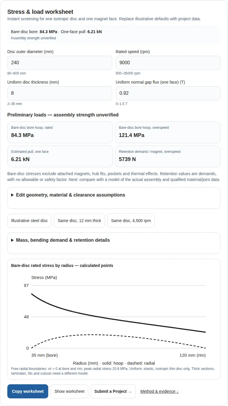
To reproduce, restore the illustrative preset, open the assumptions and mass/load disclosures, and copy the worksheet. The rated bore hoop result is 84.33 MPa, the overspeed result is 121.44 MPa, and retention demand is 5,739 N per sector. Actual rim stiffness, retention capacity and hot material allowables remain unknown. The responsible publisher is the CustomMotorDesign Engineering Team; no independent reviewer or hardware validation is claimed. Review this model by 3 November 2027, or earlier if its equations, input assumptions or source scopes change.
Formulas and numeric scenarios are the site's explicitly bounded analytical implementation. Reported loads are inputs to further engineering judgment. Unknown retention capacity, material allowables and operating gap remain unknown until project evidence is supplied.
13. Engineering handoff
Conceptual workflow, not simulation or measured performance. There is no direct drawing-release route from a calculator result.
Copy or display the worksheet, record which material and load inputs are assumptions, and attach the available assembly requirements through the Submit a Project inquiry. Include topology, support geometry, speed/duty, cold/hot conditions, magnet and retention details, and available test evidence. Unknown parameters are acceptable for feasibility discussion. Review scope, deliverables, validation costs and schedule are agreed for the project.
Rotor disc screening FAQ
What does this rotor disc stress calculator establish?
It screens free-annulus elastic self-stress, one-face magnetic pull and magnet centrifugal demand. It does not rate assembly strength, retention capacity, fatigue life or operating clearance.
Why is the bare-disc hoop stress highest at the bore?
For the uniform isotropic free annulus used here, the classical plane-stress solution peaks at the inner radius. Hub fits, keyways and pockets change that stress field and need separate analysis.
What changes at 1.2 times rated speed?
At unchanged geometry and material density, centrifugal demand and elastic self-stress increase by 1.2 squared, or 44%. The multiplier is a user assumption, not a universal qualification requirement.
Does a dual-rotor layout remove disc bending?
No. In a symmetric SSDR assembly, net shaft thrust may balance while each rotor is still attracted toward the central stator. Each disc and the complete bearing load path must be assessed.
How is a central rotor between two stators handled?
For DSSR, the worksheet reports one face only. Calculate both faces separately and use their spatial load difference for bending, while retaining both magnet faces in assembly mass and centrifugal loading. No fixed cancellation factor is applied.
Why is the deflection result initially unknown?
Disc rigidity does not specify the support condition or deformation shape. Supply a measured or FEA-derived effective rim stiffness for this load distribution to obtain a one-way F/k estimate. Otherwise use the required stiffness output to request analysis.
Is the default 0.18 mm bending allocation a standard?
No. It is an illustrative allocation within a 0.9 mm nominal gap. The OEM must reserve additional clearance for runout, bearing motion, thermal growth and dynamic response.
Can bond shear demand be compared directly with a lap-shear datasheet?
A nominal force divided by bond area is not a joint allowable. Substrate, preparation, bondline, temperature, peel and fatigue require representative joint analysis and qualification. See ASTM D1002 in the evidence table for its test scope.
Does choosing a sleeve or pocket guarantee retention?
No. Sleeve layup and interference, pocket geometry, contact stresses, fasteners and manufacturing tolerances determine capacity. These are outside the load-demand worksheet.
Can aluminum or titanium replace magnetic back iron?
They may serve as structural carriers, but they do not provide the ferromagnetic return path of a conventional iron-backed design. Additional magnetic components change mass, joints and stiffness. Conductive titanium is not free of eddy-current losses.
Can CFRP or a lamination stack use this isotropic disc model?
No. Orthotropic composite layups and joined lamination stacks need appropriate constitutive, contact and failure models. The editable scalar elastic properties are for a uniform isotropic disc.
What should accompany an engineering inquiry?
Copy the worksheet and provide the topology drawing, supported hub geometry, temperature range, magnetic load map, retention details and available test data. Unknown inputs may be identified for feasibility review.
Categories
More Posts

Frameless Torque Motor Integration: Rotor Bonding, CTE Mismatch, and Runout Control Guide
Plan frameless torque motor bonding, CTE mismatch and runout control. Use the OEM checklist to compare retention methods and prepare an engineering review.

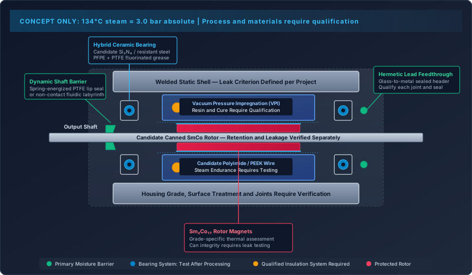
Autoclavable BLDC Motor Design: Steam Sterilization Resistance, Hermetic Sealing, and Bearing Grease Longevity Guide
Autoclavable BLDC motor design guide to steam resistance, hermetic sealing and bearing grease life. Use the checklist to prepare your OEM engineering review.

Robot Joint Module Thermal Dissipation: Harmonic Drive Heat Trapping, Grease Limits, and Actuator Duty Cycle Budgeting
Plan robot joint module thermal dissipation with grease limits, heat-path checks, and a worked duty-cycle example. Prepare an OEM actuator engineering brief.