
Autoclavable BLDC Motor Design: Steam Sterilization Resistance, Hermetic Sealing, and Bearing Grease Longevity Guide
Autoclavable BLDC motor design guide to steam resistance, hermetic sealing and bearing grease life. Use the checklist to prepare your OEM engineering review.
1. Executive Summary: The 134°C Moist Heat Sterilization Challenge for Medical Motors
Autoclavable brushless DC (BLDC) motor design requires treating steam sterilization as a complete reprocessing duty: cleaning chemicals, heat, pressure reversals, moisture and drying all affect the assembly. A high temperature rating alone cannot establish steam resistance, bearing grease longevity or a reusable handpiece's service life.
This guide is for medical device engineers and OEM buyers comparing motors for surgical handpieces, orthopedic tools and other reusable powered instruments. Its global scope covers component selection and supplier qualification; local requirements and the finished device's validated instructions for use (IFU) determine the actual reprocessing conditions. Motors are assumed to be unpowered during sterilization. Radiation, ethylene oxide and low-temperature peroxide processes require separate assessments.
Evidence and limits — reviewed 5 November 2026: The cited primary sources establish sterilization, washer-disinfector and lubricant context. The selection tables and qualification workflow below are engineering synthesis, not measured CustomMotorDesign endurance results. No cycle life, clinical suitability or certification is claimed for an illustrated motor. A target such as 1,000 cycles is a buyer requirement until representative assemblies have passed an agreed test plan.
The practical selection sequence is:
- Define the complete cleaning, steam, drying and operating duty.
- Decide which volumes exclude moisture and which must tolerate and drain it.
- Select bearings, lubricant, magnets and insulation as a compatible system.
- Compare supplier evidence against the same assembly configuration and acceptance criteria.
For an active project, request an engineering review with your torque-speed duty, available envelope and proposed reprocessing profile.
2. The Autoclave Sterilization Environment: Process Standards and Motor Stress
ISO 17665:2024 addresses development, validation and routine control of moist heat sterilization processes. It replaces the older ISO 17665-1:2006 and associated technical specifications. It does not award an electric motor an endurance rating. EN 285 concerns large steam sterilizers; healthcare practice guidance and device-specific IFUs address different parts of the reprocessing workflow. These documents are not interchangeable motor specifications.
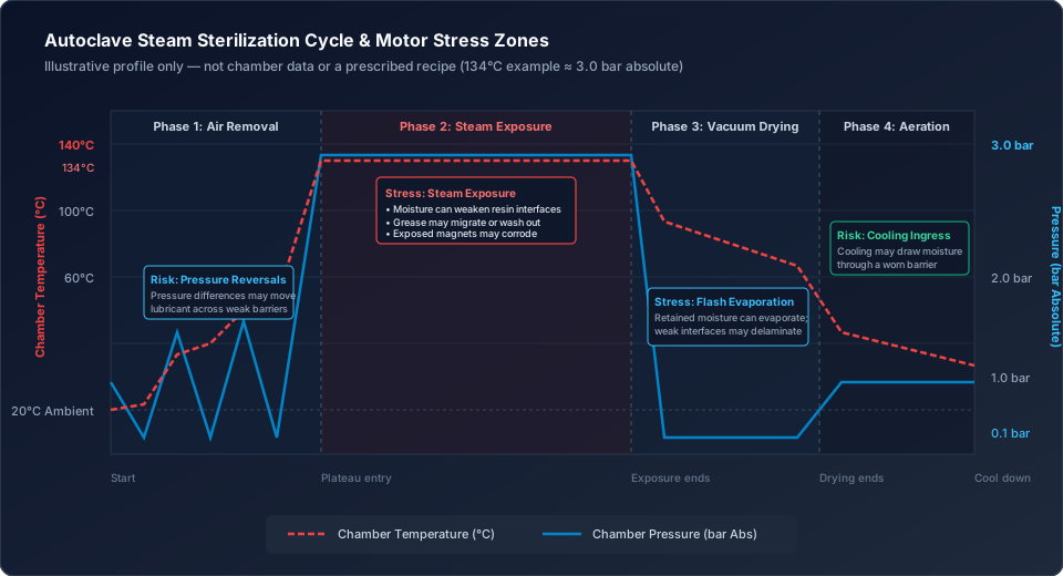
Phase 1: Pre-Vacuum Air Removal
Vacuum and steam pulses change pressure across housings, seals and internal cavities. A sealed volume and a vented volume experience different differential pressures; chamber pressure alone does not describe the load on each barrier. Specify evacuation depth in absolute units, pulse count, ramp rates and assembly orientation. Inspect for lubricant migration and moisture entry rather than assuming that a shielded bearing is sealed.
Phase 2: Saturated Steam Exposure
A 134°C exposure is one relevant design case, not a universal processing requirement. Saturated steam at 134°C is approximately 3.0 bar absolute, or 2.0 bar gauge near sea level. At 137°C, saturation pressure is approximately 3.3 bar absolute; do not pair a 134–137°C range with a fixed 3.0 bar specification. Record temperature and pressure together, including tolerances and the distinction between chamber readings and actual component temperature.
Holding time depends on the validated process and load. Do not select an extended exposure or a prion protocol from this guide. For engineering endurance tests, reproduce the applicable exposure and its preceding cleaning and subsequent drying stages.
Phase 3: Post-Vacuum Drying
Reduced pressure promotes evaporation of retained water. Moisture, weak resin interfaces and thermal expansion mismatch can contribute to blistering or delamination. A single vapor expansion multiplier cannot predict stress inside a partially vented winding void. Check the assembly's drainage, residual moisture and insulation behavior after the defined drying phase.
Phase 4: Aeration and Cooling
Pressure equalization and cooling can draw condensate across a worn seal or leave water in poorly drained pockets. Record cooldown time and the permitted time before powered operation. Test representative orientations, cable routing and connectors because an exposed component tested alone may dry differently from a motor enclosed inside a handpiece.
3. Root Failure Modes: What to Inspect After Reprocessing
There is no defensible universal claim that ordinary BLDC motors fail after a particular number of autoclave cycles. Construction and exposure differ too much. Use this matrix to identify failure hypotheses and the evidence needed to accept a proposed solution.
| Motor subsystem | Potential failure mechanism | Engineering option | Evidence to request |
|---|---|---|---|
| Rolling bearings | Ring corrosion, preload change, wear or contamination | Corrosion-resistant rings; evaluate hybrid ceramic rolling elements | Bearing grade, fits, clearance analysis and post-cycle vibration/current results |
| Bearing grease | Washout, migration, oil separation or loss of lubricating film | Compare exact grease grades, including PFPE/PTFE candidates | Fill definition, cleaning compatibility and complete-cycle bearing tests |
| Magnet wire | Moisture-assisted loss of insulation resistance or coating degradation | Compare steam-tested polyimide, PEEK and other insulation systems | Wire construction and dielectric results after repeated processing |
| Stator impregnation | Moisture uptake, interfacial separation and thermal fatigue | Controlled vacuum impregnation or encapsulation | Resin identity, cure records, sections and conditioned electrical tests |
| Rotor magnets | Corrosion, coating damage or irreversible flux loss | Evaluate SmCo or protected high-coercivity NdFeB | Grade curves, retention design and post-cycle torque/back-EMF checks |
| Shaft barrier | Wear, permeation, pressure-driven ingress or blocked drainage | Contact seal, static processing closure or drainage architecture | Complete barrier definition and ingress tests before and after endurance |
| Feedback and leads | Package ingress, connector corrosion or bond failure | Protected sensors, sealed feedthroughs or suitable sensorless control | Startup, feedback accuracy and connector inspection after processing |
Dry thermal insulation classes describe one dimension of endurance. They do not specify resistance to steam, alkaline detergent or repeated pressure cycling. Likewise, a general ingress-protection rating does not by itself demonstrate autoclave compatibility. Ask what was exposed, how it was assembled and how failure was defined.
4. Bearing System Design: Grease Chemistry, Ceramic Hybrids and Preload
Bearing selection must connect operating speed and load with the state of the bearing after reprocessing. A chemically resistant lubricant can still perform poorly if its viscosity, quantity or replenishment behavior is wrong for a miniature high-speed bearing.
4.1 Lubricant Chemistry: Screen the Exact Grade
The manufacturer's Krytox product guide identifies PFPE lubricant families with different viscosity, temperature and application characteristics. This supports screening PFPE candidates, not assigning a cycle-life rating to every fluorinated grease. Obtain the exact grade's technical data and ask the lubricant and bearing suppliers to review the actual cleaning and operating duty.
| Lubricant family | Selection question | Main qualification concern |
|---|---|---|
| Mineral-oil grease | Does the exact formulation have relevant steam and wash data? | Water exposure, retention and viscosity after processing |
| PAO-based grease | What evidence covers its thickener and additives? | Separation, migration and performance after repeated cleaning |
| Ester-based grease | Has hydrolytic stability been demonstrated for this formulation? | Chemical degradation under the specified exposure |
| Silicone-based grease | Is load capacity suitable for this bearing and speed? | Film formation, migration and materials compatibility |
| PFPE/PTFE grease | Which viscosity, additive package and fill suit the bearing? | Drag, corrosion protection and retention despite chemical stability |
| Dry-film or solid lubricant | Can the coating support the required rolling-contact duty? | Wear debris, coating durability and load-dependent friction |
Do not mix lubricant families without an approved conversion procedure. Residual manufacturing oil, cleaning solvent or previous grease can change performance. Define bearing cleaning, drying, grease application and storage as controlled manufacturing steps.
4.2 Optimizing Grease Fill Quantity
A universal 15–22% fill recommendation is inappropriate without bearing geometry and supplier guidance. State whether fill means a fraction of internal free volume or a mass per bearing, and define how production measures it. Overfilling can increase churning and temperature; underfilling can limit replenishment.
Compare candidate fills using running torque, no-load current, bearing temperature, noise and lubricant retention across the planned reprocessing sequence. Establish limits before testing. A rise in no-load current needs diagnosis because seal friction, winding condition and bearing preload can produce similar symptoms.
4.3 Hybrid Ceramic Bearing Construction
Silicon nitride rolling elements are candidates for reducing some corrosion and adhesive-wear risks. Steel rings, cages and shields still require protection, and ceramic balls do not make a bearing immune to contamination or fatigue. Compare corrosion-resistant ring grades such as nitrogen-alloyed bearing steels with the actual detergent and water quality.
Calculate clearance and preload across fits, shaft and housing expansion, gradients and operating loads. Differential expansion does not automatically preserve clearance. Include both the static sterilization condition and the hottest powered operating condition, then verify drag and vibration on representative assemblies.
5. Hermetic Sealing and Barrier Architectures
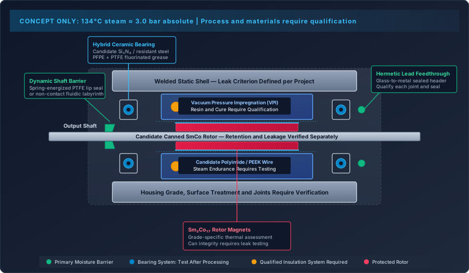
A welded stationary enclosure can be assessed for hermetic leakage. A rotating output shaft with a polymer lip seal is a different boundary: wear, permeation and operating motion remain relevant. Describe which subassembly is hermetic instead of calling the entire motor hermetic because its shell is welded.
5.1 The Three-Barrier Isolation Approach
One useful architecture divides protection into three functions. First, the shell, rear feedthrough and shaft interface control external entry. Second, bearing protection and a sealed rotor can reduce damage if moisture reaches an internal volume. Third, winding insulation and encapsulation preserve electrical isolation under the specified conditioning.
These barriers can share common failure causes, including thermal expansion, assembly damage and detergent exposure. Define interfaces and drainage paths rather than assuming three barriers provide three independent guarantees. Set a leak-rate criterion for each sealed volume from its moisture budget, free volume and expected exposure; no generic helium threshold establishes complete motor life.
5.2 Dynamic Shaft Sealing: Contact Seals vs. Labyrinths
Spring-energized PTFE seals are candidates where friction and wear are acceptable. Obtain supplier limits for the compound, shaft finish, hardness, temperature, pressure differential and lubrication condition. RPM alone cannot set the boundary because surface speed depends on shaft diameter.
A non-contact labyrinth reduces rubbing losses but is not a hermetic steam barrier. Its success depends on the protection of downstream components and verified drainage. If a removable processing cap is used, test installation errors and its stated service life as part of the device workflow.
5.3 Housing Materials: 316L vs. 17-4PH
316L and 17-4PH offer different corrosion, strength, machining and heat-treatment trade-offs. Specify material condition, weld procedure and surface treatment together. Neither grade is universally immune to chlorides or cleaning chemistry. Check crevices, dissimilar-metal interfaces and bearing-seat geometry after repeated processing. A salt-spray result alone cannot establish resistance to the actual hospital reprocessing sequence.
6. Magnetic Circuit and Rotor Retention: SmCo vs. Protected NdFeB
Choose a magnetic system from the grade's demagnetization curves, magnetic load line, operating current and corrosion protection. A catalog maximum temperature or Curie temperature does not establish an assembled rotor's working limit.
| Selection factor | SmCo candidate | Protected high-coercivity NdFeB candidate | Buyer decision |
|---|---|---|---|
| Temperature stability | Often favorable; grade-specific | Requires grade and operating-point assessment | Request curves at relevant temperatures |
| Steam exposure | Corrosion behavior still needs qualification | Coating and enclosure integrity are critical | Test the actual protected assembly |
| Flux and torque | Depends on grade and geometry | May offer a useful energy-product advantage | Compare the finished electromagnetic design |
| Mechanical integrity | Brittle material needs retention review | Retention and coating handling need review | Require overspeed and balance evidence |
| Protective can | May still be required | Can isolate magnets from moisture | Evaluate welds, leakage and added air gap |
| Procurement | Cost and availability depend on specification | Coating, canning and inspection add cost | Compare total qualified assembly cost |
6.1 Moisture Damage in NdFeB
Water reaching susceptible magnet material can cause corrosion and loss of integrity. Coating defects and unprotected edges deserve inspection. This guide does not assign a fixed number of cycles to magnet disintegration or claim that one hydrogen reaction predicts field life. Review microscopy, coating quality and magnetic measurements from the proposed assembly.
6.2 Why Consider Sm₂Co₁₇?
SmCo can offer useful temperature stability, but it is not universally corrosion-proof and cannot guarantee unchanged torque after thousands of procedures. Compare back-EMF or torque constant at the same reference temperature before and after exposure. Separate reversible hot-temperature behavior from irreversible demagnetization and mechanical damage.
6.3 Mechanical Retention: Canned Rotors
Adhesives, mechanical sleeves and welded cans each require application-specific assessment. A retaining sleeve is not automatically hermetic. A welded can adds inspection needs and can alter air gap, balance and eddy-current loss. Titanium and suitable stainless steels are options; wall thickness and weld configuration must follow stress, electromagnetic and manufacturing analysis. Custom 465 is a precipitation-hardening stainless steel, not an austenitic substitute for 316L.
7. Stator Winding and Insulation: Qualify the Complete System
7.1 Magnet Wire Insulation Selection
Polyimide and PEEK constructions are candidates for demanding insulation systems, but their names alone do not establish steam resistance or a thermal class for the complete winding. Obtain the exact wire construction, coating thickness, termination method and compatibility with slot liners and encapsulant. Inspect bend damage and stripped lead exits, where a robust wire coating can still leave a weak interface.
7.2 Vacuum Impregnation and Encapsulation
Vacuum impregnation can reduce trapped air and improve resin penetration. It cannot guarantee zero voids or permanent moisture exclusion. Use the resin supplier's process window to define pre-drying, degassing, viscosity, vacuum/pressure stages and cure. A generic time-temperature recipe can undercure one resin and damage another assembly.
Confirm cure and wet-conditioned behavior, inspect representative sections or suitable imaging, and correlate defects with electrical performance. Glass-transition temperature is a screening parameter, not a steam-life certificate. USP Class VI material data also do not establish the biological safety or reprocessing suitability of the finished medical device.
8. Slotted vs. Slotless Motor Topology Trade-offs
Topology affects torque production and control, but it does not independently determine autoclave cycle life. Compare both candidates under the same envelope, duty and barrier requirements.
| Engineering parameter | Slotted BLDC architecture | Slotless BLDC architecture | Evidence needed |
|---|---|---|---|
| Winding support | Slots support and constrain the winding | Winding support depends on its formed and bonded structure | Post-cycle inspection of support and encapsulation |
| Reprocessing endurance | Depends on materials and barriers | Depends on materials and barriers | Equivalent complete-assembly endurance tests |
| Cogging torque | Tooth interaction can create cogging | Removing stator teeth reduces this source of cogging | Measured torque ripple with the proposed drive |
| High-speed losses | Iron loss and rotor heating need analysis | Copper, rotor and remaining iron losses still matter | Speed-dependent temperature and efficiency data |
| Low-speed torque | Depends on active geometry and cooling | Depends on winding loading and cooling | Continuous and peak duty measurements |
| Inductance and drive | Geometry-dependent current ripple | Low inductance may challenge current control | Inverter matching, ripple and startup verification |
For a related architecture discussion, see custom coreless and slotless motors. Select topology after comparing usable torque and thermal limits, not from unsupported cycle-life rankings.
9. Medical OEM Engineering and Procurement Verification Checklist
Use this checklist to make supplier quotations comparable before releasing drawings or ordering qualification samples.
- Reprocessing duty: Record the applicable IFU, temperature, absolute pressure, exposure, vacuum pulses, drying, cooldown and required number of complete cycles.
- Cleaning duty: Specify detergent identity, concentration, water quality, temperature, rinse and mechanical exposure rather than a generic pH range.
- Bearing system: Identify ring, ball and cage materials, fits, clearance/preload, grease grade and measured fill quantity.
- Moisture architecture: Mark sealed, vented and drained volumes; include connectors, cable exits and any processing closures.
- Rotor: Document magnet grade, protection, retention, balance and magnetic acceptance limits at a defined reference temperature.
- Insulation: Identify wire, liners, resin and terminations; obtain process records and conditioned electrical evidence.
- Acceptance limits: Agree speed, torque, no-load current, bearing temperature, vibration and electrical limits before endurance testing.
- Safety tests: Have the device safety team define insulation resistance, dielectric withstand and leakage tests for the actual insulation architecture and test condition.
- Sample coverage: Agree sample count, manufacturing lots, worst-case variants, control samples and failure handling. One surviving prototype is not a reliability demonstration.
- Change control: Require lot traceability and written change notification for grease, wire, resin, magnets, seals and critical processes.
Bring this completed checklist to a medical motor project review so open requirements can be resolved before the sample test schedule is committed.
10. Procurement Specification Ledger and Qualification Method
A quotation should separate the requested target, supplier evidence and remaining qualification work. Use this ledger rather than converting material choices into an unsupported guarantee.
| System parameter | RFQ input | Verification method | Acceptance boundary |
|---|---|---|---|
| Steam endurance | Full cycle profile and required count | Logged exposure of representative assemblies | Cycle count alone does not demonstrate sterility or reliability |
| Cleaning resistance | Exact chemistry and wash/rinse sequence | Inspection and function after combined processing | No universal detergent compatibility |
| Housing and joints | Grade, treatment, welds and interfaces | Corrosion, dimensional and joint inspection | Salt spray alone is insufficient |
| Sealed volumes | Defined boundary and moisture budget | Agreed leak method before and after cycling | Static leakage does not qualify a dynamic seal |
| Bearing system | Speed/load duty, grease and preload | Current, torque, temperature and vibration trends | Lubricant data alone do not establish bearing life |
| Electrical insulation | Device-specific limits and conditioning | Resistance and withstand tests under the approved plan | No universal 1,000 V or 100 MΩ acceptance rule |
| Rotor assembly | Grade, retention and torque requirements | Reference-temperature magnetic and mechanical checks | Hot measurements must be normalized appropriately |
| Feedback and connector | Startup/load duty and interface requirements | Repeated startup and feedback checks after processing | Component temperature rating is insufficient |
A Reproducible Qualification Sequence
Begin with a frozen configuration: record drawings, serial numbers, material lots, grease fill and assembly process. Measure baseline performance using a controlled voltage, controller, load and ambient temperature. Expose samples to the full cleaning, steam and drying sequence in representative fixtures and orientations. Interleave operating duty where the intended service involves use between reprocessing cycles.
Choose inspection checkpoints in advance, with earlier checkpoints if initial degradation is expected. Record chamber profiles, actual completed cycles, failures and deviations. Trend results against baseline and absolute acceptance limits; do not discard failed samples from the denominator. After the final checkpoint, inspect barriers, bearings, rotor protection and winding interfaces to distinguish wear from moisture damage.
Illustrative scheduling calculation: If the buyer requires 1,000 cycles and the complete chamber sequence takes 70 minutes, chamber occupancy alone is 1,000 × 70 / 60 = 1,166.7 hours. If each cycle includes a four-minute plateau, plateau exposure totals only 1,000 × 4 / 60 = 66.7 hours. These assumed inputs demonstrate why plateau time cannot substitute for full-cycle scheduling; they are not test results. Add handling, operating tests, maintenance and failed-run allowances separately.
The OEM reliability team should set sample size and confidence requirements for the intended claim. Testing multiple motors in one chamber run also introduces shared exposure conditions. Accelerated testing needs a justified failure model; increasing temperature or skipping cleaning can change the failure mechanism rather than reproduce normal service faster.
11. Frequently Asked Questions
Can an autoclavable motor use Hall-effect sensors?
Potentially, if the complete sensor, package, leads and protective enclosure survive the required processing. A semiconductor junction rating does not qualify its packaging. Sensorless control can remove some exposed electronics, but back-EMF estimation has limitations at zero and low speed. Verify loaded startup, reversal and low-speed control rather than assuming sensorless FOC solves every surgical drive requirement.
Is SmCo always better than NdFeB?
No. SmCo is a candidate when temperature stability matters; protected high-coercivity NdFeB may suit other magnetic and packaging requirements. Compare grade-specific curves, corrosion protection, retention and finished motor performance. Neither chemistry establishes a cycle-life guarantee without assembly testing.
What causes bearing noise after repeated autoclaving?
Possible causes include corrosion, contamination, grease migration, preload changes and mechanical wear. Compare no-load current, vibration spectra and temperature under controlled conditions, then inspect the bearing and lubricant. Noise alone cannot identify the root cause or assign a particular failure cycle count.
Does the entire motor have to be hermetic?
No universal architecture is required. Some designs protect stationary volumes while allowing controlled drainage elsewhere. A dynamic lip seal is not equivalent to a welded hermetic enclosure, and a labyrinth does not block steam by itself. The relevant question is whether every exposed component and interface meets the agreed complete-cycle acceptance criteria.
How does automated washing affect selection?
ISO 15883-1:2024 addresses general washer-disinfector performance, with load-specific requirements in other parts. It does not prescribe one detergent recipe for every motor. Obtain the device's actual cleaning conditions and assess seals, lubricant retention, coatings and drainage before evaluating steam exposure in isolation.
Can optical encoders be integrated?
Only with evidence for the complete encoder and its protection under the specified processing. Optical, magnetic and inductive technologies have different packaging and alignment risks; none is automatically steam-proof. Consider whether the feedback assembly can remain outside the reprocessed volume while preserving required accuracy.
Does vacuum impregnation prevent all insulation failures?
No. It can improve resin penetration, but cure quality, interfaces, moisture absorption and thermal expansion remain relevant. Inspect representative parts and perform the approved electrical tests after defined conditioning. Do not adopt a damp high-voltage test recipe without device-specific safety review.
What shaft speed can a PTFE seal tolerate?
Use the seal supplier's pressure, temperature and surface-speed envelope. For a 4 mm shaft at 40,000 RPM, v = π × 0.004 × 40,000 / 60 ≈ 8.38 m/s. This is a kinematic calculation, not seal approval. Contact geometry, shaft finish, wear, lubrication and sterilization exposure can still make the application unsuitable.
12. Primary Standards and Authoritative References
These public primary-source pages establish scope and product-family context. Detailed acceptance criteria require the applicable standards, supplier data and OEM qualification plan. Selection judgments and example calculations in this guide are explicitly engineering synthesis.
| Source | What it supports | What it does not establish |
|---|---|---|
| ISO 17665:2024 — Moist heat sterilization | Sterilization process development, validation and routine control; replaces the earlier 17665 publications | Motor cycle life, a universal chamber recipe or a component certification |
| ISO 15883-1:2024 — Washer-disinfectors | General cleaning/disinfection equipment requirements and validation context | One universal detergent, motor sealing dimensions or steam endurance |
| Chemours Krytox — High-performance lubricants product guide | PFPE lubricant families and grade-dependent selection | Medical device approval, universal grease fill or assembled bearing cycle life |
Revisit this guide when the process specification, material formulation or cited standard changes; otherwise review the selection assumptions within 12 months. For a global program, the OEM quality team should confirm which editions and local adoptions govern each market.
13. Request an Engineering Review and Co-Development Hand-off
Send your dimensional envelope, voltage, torque-speed duty, feedback requirements and complete reprocessing profile through Submit an Engineering Inquiry. Include the required life claim, sample quantity and existing test evidence so engineering can identify feasibility gaps and propose a qualification scope.
Explore special-environment and medical motor design for application context and testing and production planning for the development hand-off. Confirm available tests, facilities and deliverables in the project quotation; this guide does not promise specific in-house certification or clinical validation services.
Categories
More Posts

Robot Joint Module Thermal Dissipation: Harmonic Drive Heat Trapping, Grease Limits, and Actuator Duty Cycle Budgeting
Plan robot joint module thermal dissipation with grease limits, heat-path checks, and a worked duty-cycle example. Prepare an OEM actuator engineering brief.


Frameless Torque Motor Integration: Rotor Bonding, CTE Mismatch, and Runout Control Guide
Plan frameless torque motor bonding, CTE mismatch and runout control. Use the OEM checklist to compare retention methods and prepare an engineering review.

Axial Flux Motor Rotor Disc Stress & Magnet Retention Calculator
Screen axial flux motor rotor disc stress, magnetic bending and magnet retention loads with explicit assembly limits. Copy the worksheet and submit a project.