

Frameless Torque Motor Integration: Rotor Bonding, CTE Mismatch, and Runout Control Guide
Plan frameless torque motor bonding, CTE mismatch and runout control. Use the OEM checklist to compare retention methods and prepare an engineering review.
1. Executive Summary: Why Frameless Motor Kits Fail at the Mechanical Interface
Frameless torque motor integration makes the OEM responsible for the shaft, bearings, housing, rotor retention and cooling interfaces. Select the retention method from the required torque, temperature cycle and service plan; then check bond clearance and assembled runout against the motor supplier's drawing. An adhesive's catalogue strength alone cannot approve the joint.
This guide helps mechanical engineers and sourcing teams compare rotor bonding, thermal expansion and inspection requirements for radial-flux frameless kits. Three questions should be resolved before ordering machined parts:
- CTE mismatch: Will the shaft and rotor bore grow differently enough to close or open the intended bond gap?
- Runout control: After bearing motion, load deflection and thermal growth, what minimum radial air gap remains?
- Assembly and service: Can the joint be cured, inspected and eventually removed within the limits of every motor component?
Reviewed: October 28, 2026. Scope: global OEM engineering and procurement. The arithmetic below uses stated hypothetical inputs; it is not measured motor performance, a product rating or a universal acceptance standard. Confirm materials, adhesive data and drawing revisions for the selected kit. Axial-flux assemblies and housed motors need their own geometry and load models.
Cover image: AI-edited supplier reference showing separate rotor and stator components; it does not establish a supplied model or rating.
For an active design, submit a frameless integration brief with the envelope, torque duty and temperature range. Use the checklist below to identify missing inputs first.
2. Radial Thermal Expansion Stackup and CTE Mismatch
A radial-flux rotor may combine magnets, back iron and a customer hub. Confirm the actual construction: a lamination stack, solid sleeve and magnet retaining sleeve have different stiffness and expansion behavior.
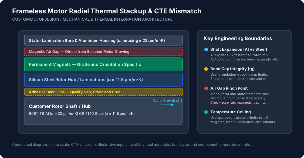
Conceptual layer diagram, not a dimensional drawing or thermal simulation.
2.1 Differential Radial Expansion: A Reproducible Example
For a first screening calculation, use radial growth = interface radius × CTE × temperature change. Express CTE in 1/K, radius in mm and temperature change in K. For approximately equal interface radii:
radial gap closure = r × (shaft CTE × shaft ΔT − rotor CTE × rotor ΔT)A positive result means the shaft grows toward the bore; a negative result opens the gap. This free-expansion estimate omits adhesive compliance, constraint, temperature gradients and ovality. It does not calculate bond stress.
Illustrative inputs: 40 mm interface radius, aluminum CTE 23.2 × 10⁻⁶/K, steel CTE 11.5 × 10⁻⁶/K, and both parts heated from 20°C to 90°C. Radial closure is 40 × (23.2 − 11.5) × 10⁻⁶ × 70 = 0.03276 mm, or 32.76 µm. Diametral clearance decreases by 65.52 µm. An initial 0.100 mm diametral clearance would therefore become approximately 0.03448 mm before elastic constraint is considered.
Do not compare a radial calculation directly with a diametral fit allowance. For concentric parts, radial bond thickness is half the diametral clearance. Repeat the calculation at cold start and with separate shaft and rotor temperatures. Opening at cold temperature can load the bond in tension; local geometry can introduce peel and shear.
2.2 Shaft and Housing Material Compatibility Matrix
Use this qualitative matrix to shortlist hub materials. Obtain grade-, condition- and temperature-specific CTE data before calculating a fit; the worked example's assumed values are not a material specification.
| Shaft / Hub Material | Expansion Relative to a Steel Rotor at Equal Temperature Rise | Procurement / Engineering Check |
|---|---|---|
| 6061-T6 aluminum | Usually higher | Check hot gap closure, coating adhesion and thermal cycling. |
| 7075-T6 aluminum | Usually higher | Higher strength does not eliminate thermal mismatch; check corrosion protection. |
| 4140 / 4340 alloy steel | Often closer | Verify actual rotor alloy, heat treatment, mass and magnetic interaction. |
| 303 / 304 stainless steel | Usually higher | Check CTE and surface condition; machining can affect magnetic behavior. |
| 416 / 420 stainless steel | Often closer | Confirm heat treatment, corrosion needs and flux-path effects. |
| Ti-6Al-4V titanium | Usually lower | Check hot gap opening, surface preparation and stiffness. |
| Invar 36 | Much lower near room temperature | Check expansion over the full temperature interval and bond strain. |
3. Retention Architectures: Adhesive, Mechanical Clamp, or Shrink Fit
Selecting how to transmit torque from the rotor to the shaft without inducing out-of-round distortion is the core structural decision of frameless integration.
| Retention Method | When to Evaluate It | What Must Be Qualified | Service Tradeoff |
|---|---|---|---|
| Anaerobic retaining compound | Close-fitting cylindrical metal joints | Actual gap, substrate cure, hot strength, fatigue and torque capacity | Removal may require heat incompatible with the motor. |
| Toughened structural epoxy | A controlled bond layer with thermal mismatch | Gap control, creep, cure shrinkage and thermal cycling | Removal can damage the hub or magnets. |
| Axial friction clamp and shoulder | Serviceability is a priority and space permits | Contact geometry, preload, slip and ring distortion | Accessible fasteners help servicing; additional parts add inertia. |
| Thermal shrink / interference fit | The motor supplier permits the fit | Hoop stress, roundness, assembly temperature and hot/cold retention | Removal can damage a thin rotor ring. |
| Keys, splines or set screws | A purpose-designed structural hub exists | Local stress, fatigue, balance and separation from the magnetic ring | Do not machine these features into an unapproved thin rotor ring. |
3.1 Fit Classes Do Not Define a Bond Gap by Themselves
A label such as H7/h6 does not guarantee a fixed clearance band at every diameter, and size tolerance alone does not control coaxiality. Use ISO 286-1 fit terminology, calculate minimum and maximum shaft/bore limits at the actual basic size, and specify the bearing datum and geometric controls separately. Release the drawing only when the complete tolerance stack stays within the qualified joint window.
4. Adhesive Selection and Process Control
Shortlist a chemistry, then qualify the exact formulation on the actual coating and joint geometry. The Henkel LOCTITE 648 technical data sheet, May 2021 reports substrate- and gap-dependent cure and includes passive-metal performance. Its 31 MPa steel pin-and-collar result follows 72 hours at 23°C; it is not an allowable stress for an operating motor joint.
Use the following comparison fields when requesting adhesive proposals. Do not rank a cylindrical retaining test and an epoxy lap-shear test as equivalent joint ratings.
| Selection Field | Anaerobic Retaining Compound | Toughened Structural Epoxy | Evidence to Request |
|---|---|---|---|
| Gap definition | Cure depends on confined metal-joint geometry | Layer thickness affects stiffness and strain | Qualified gap band; state radial or diametral convention. |
| Substrate / coating | Surface activity and activator can affect cure | Surface preparation governs adhesion | Coupons with the actual coating and cleaning process. |
| Torque transmission | Cylindrical shear data is a starting point | Lap-shear data is a starting point | Joint-level torque, fatigue and overload validation. |
| Thermal mismatch | Check strain and hot/cold retention | Check compliance, creep and ageing | Thermal-cycle test of the complete assembly. |
| Process window | Check fixture time and full cure | Check mix ratio, pot life and full cure | Controlled work instruction and batch traceability. |
| Temperature / rework | Removal heat may exceed motor limits | Cure or removal can affect other bonds | Component temperature limits and a qualified service plan. |
4.1 Chemical Activation of Inactive Surfaces
Anaerobic formulations differ in passive-metal performance. Follow the selected adhesive's preparation and activator instructions; do not impose one primer, roughness or flash-off time on all coated hubs. Validate dispensing, squeeze-out direction, full cure and post-cure runout on trial assemblies. Keep residue and cleaning solvent away from insulation and the active air gap.
Use a separate centering datum or fixture to hold the rotor concentric during cure; liquid adhesive does not locate the rotor. If substrate data or gap limits are missing, request an integration review before freezing the hub drawing.
5. Air Gap Tolerancing, Runout, and Unbalanced Magnetic Pull (UMP)
Take nominal radial air gap from the selected motor drawing. Distinguish uniform thermal gap change, center offset, surface runout and bearing motion before combining allowances.
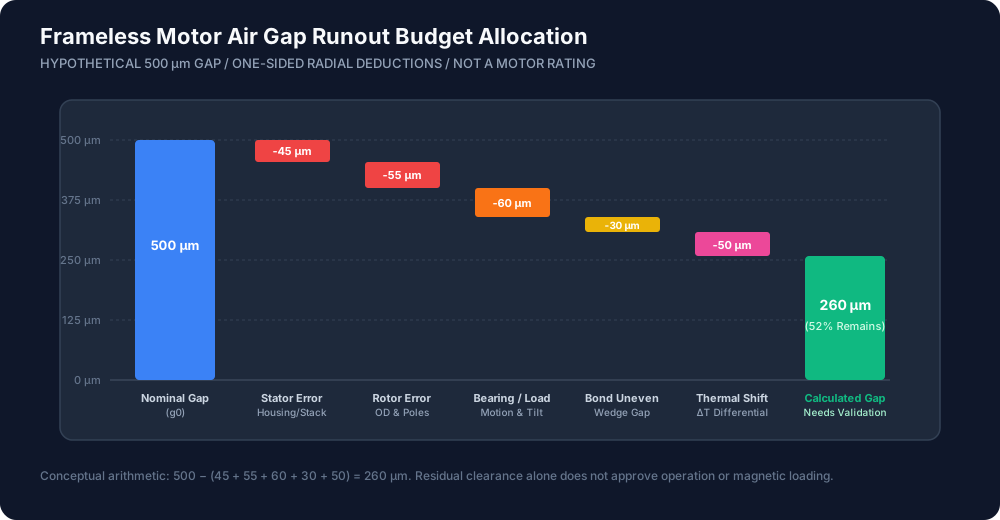
5.1 The Unbalanced Magnetic Pull (UMP) Mechanism
For ideal circular surfaces with center offset e, local gap ranges from g₀ − e to g₀ + e. A narrower gap can produce asymmetric magnetic attraction and additional bearing load. Force and torque-ripple changes depend on the magnetic circuit, current and geometry; neither a fixed force nor a cogging multiplier follows from eccentricity alone. Request electromagnetic analysis or measurement if these loads affect the bearing or positioning specification.
5.2 Five-Contributor Radial Clearance Budget
The diagram and table use the same hypothetical 500 µm nominal gap. Each deduction is already a maximum one-sided radial clearance reduction. These allocations are independent of the thermal bond example in Section 2 and do not represent catalogue motor tolerances.
| Budget Item | Assumed Radial Value | Basis to Confirm on a Real Assembly |
|---|---|---|
| Nominal radial gap | 500 µm | Minimum-size geometry from the motor drawing. |
| Stator axis / bore error | −45 µm | Bore position and form relative to the bearing datum. |
| Rotor / hub geometry | −55 µm | Rotor outer envelope relative to the shaft axis. |
| Bearing motion and load deflection | −60 µm | Installed clearance, preload, tilt and applied load. |
| Bond placement error | −30 µm | Extra centering error after cure, if not included above. |
| Thermal gap closure | −50 µm | Rotor/stator growth and housing constraint. |
| Total assumed deductions | 240 µm | 45 + 55 + 60 + 30 + 50. |
| Calculated remaining clearance | 260 µm (52%) | 500 − 240; not a validated operating margin. |
Measurement convention matters: for a circular surface with pure axis eccentricity, TIR is twice the eccentricity. Form error and tilt can invalidate that shortcut. Convert measurements to radial closing displacement before summation, and do not add bond or hub errors again if assembled rotor runout already contains them. Use ISO 1101 geometric specification rules to define datums and inspection conditions.
Set required residual clearance with the motor supplier, including uncertainty, overspeed and load cases. A positive arithmetic remainder alone does not approve magnetic loading, rub clearance or positioning performance.
6. Axial Alignment and End-Turn Clearances
Locate the active rotor and stator stacks using the supplier's axial datum. Radial clearance does not establish correct magnetic overlap or end-turn clearance.
6.1 Parasitic Axial Magnetic Forces
Axial offset can change magnetic overlap and create axial forces. Obtain a force-versus-offset estimate or test for the chosen geometry before assigning bearing preload. Do not assume a universal force per millimeter or a linear change in torque constant.
6.2 Stator End-Turn Keep-Out Zones
Keep tooling and housing features outside the supplier's end-turn envelope, including dimensional tolerance and motion. Do not react assembly force through windings, magnets or unsupported laminations; use approved structural locating surfaces.
Electrical clearance and creepage require an insulation-coordination review that considers working and impulse voltage, pollution degree, altitude, materials and insulation construction. A DC bus voltage alone cannot establish a universal clearance value or IEC compliance.
7. Guided Magnetic Insertion Tooling
Permanent-magnet attraction can pull an unsupported rotor into the stator. Plan the insertion and removal fixture before the kit arrives.
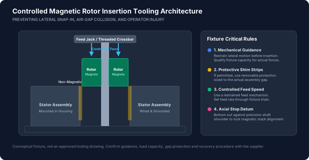
7.1 The Snap-In Phenomenon
An off-axis rotor can strike stator teeth, damage magnets or insulation, and create a pinch hazard. Restrain lateral motion before the rotor enters the magnetic circuit; fixture capacity must cover the selected assembly's forces.
7.2 Tooling Design Rules
The image is a conceptual fixture layout, not an approved tooling drawing.
- Guide and support: Use a rigid pilot and bearing-datum fixture; confirm material magnetic response and stiffness.
- Controlled feed: Use a restrained feed mechanism with a stop and a defined recovery path. Establish force capacity and feed rate through the motor supplier's procedure and fixture trials.
- Protective shims: If permitted, use clean, removable non-magnetic protection sized to the actual gap. Verify that shims cannot damage coatings or become trapped.
- Axial location: Use an approved shoulder or stop to set stack overlap. Keep the assembly centered until the joint can support handling loads.
8. Disassembly, Reworkability, and Magnet Temperature Ceilings
Agree the service strategy when selecting retention. A removable rotor-hub cartridge and a rotor bonded permanently to the machine shaft create different replacement costs.
8.1 Thermal Softening of Adhesives
The LOCTITE 648 data sheet describes localized heat around 250°C as one removal option. That adhesive instruction is not permission to heat a motor assembly to that temperature. Select a mechanical or sacrificial service strategy when the motor's approved exposure limits are lower.
8.2 Component Temperature Limits
Magnet demagnetization depends on grade, geometry, operating point, opposing field and time at temperature. Obtain supplier limits for the magnets, their original adhesive, coatings, winding insulation and feedback components. Use the most restrictive applicable limit for cure and rework; measure component temperatures during process qualification. There is no single safe cure temperature for all frameless kits.
For repeat servicing, evaluate a supplier-approved clamp or replaceable bonded cartridge. Confirm access, extraction loads and replacement inspection before design release.
9. OEM Engineering and Procurement Hand-Off Checklist
Before releasing CAD models, machining drawings, or submitting a project for frameless motor quotation, review each item on the following engineering checklist:
| Verification Item | Engineering Acceptance Criterion | Verification Method / Tool | Pass / Review Needed |
|---|---|---|---|
| 1. Shaft material & CTE | Growth checked at cold, hot and unequal component temperatures. | Material data and calculation / FEA | [ ] Pass [ ] Review |
| 2. Bond gap | Drawing limits remain inside the qualified adhesive window; radial / diametral convention stated. | Shaft and bore limit calculation | [ ] Pass [ ] Review |
| 3. Datums and surface preparation | Fit, geometry, coating and preparation defined for the actual diameter. | Controlled manufacturing drawings | [ ] Pass [ ] Review |
| 4. Clearance and runout | One-sided radial deductions and uncertainty leave supplier-agreed clearance; no double counting. | Tolerance budget and assembled inspection | [ ] Pass [ ] Review |
| 5. Axial magnetic center | Stack overlap and axial location match the selected motor drawing. | CAD dimensional chain | [ ] Pass [ ] Review |
| 6. End-turn keep-out | Mechanical envelope and electrical insulation requirements both reviewed. | Interference and insulation-coordination review | [ ] Pass [ ] Review |
| 7. Adhesive process | Formulation, batch, preparation, dispensing and cure acceptance defined. | Qualified work instruction and trial parts | [ ] Pass [ ] Review |
| 8. Assembly fixture | Alignment, force capacity, feed and extraction method approved. | Fixture trial and sign-off | [ ] Pass [ ] Review |
| 9. Cure and rework temperature | Every affected component stays within its approved exposure limits. | Instrumented process qualification | [ ] Pass [ ] Review |
| 10. Acceptance and ownership | Torque retention, runout, balance, back-EMF and required NVH checks have agreed conditions and owners. | Inspection plan with records and revisions | [ ] Pass [ ] Review |
For comparable quotations, also state prototype quantity, annual demand, duty cycle, required inspection records, responsibility for customer-supplied hubs and whether a serviceable cartridge is required. Agree deliverables and acceptance criteria before comparing price.
10. Frequently Asked Questions (FAQ)
Can I press-fit a frameless motor rotor directly onto an interference-tolerance shaft without adhesive?
Only if the motor supplier approves the joint for that rotor construction. Check interference over temperature, hoop stress, roundness, insertion force and torque retention. A generic fit class or shrink-fit temperature cannot establish suitability for a thin magnetic ring.
What is the maximum allowable radial runout before cogging torque degrades significantly?
There is no universal percentage. Specify assembled runout relative to the bearing datum, then assess minimum gap, magnetic forces and torque ripple for the actual motor and operating condition. TIR and eccentricity are different quantities; the 52% remainder in this guide is arithmetic only, not a performance threshold.
How do I prevent adhesive from migrating into the active air gap during assembly?
Qualify bead volume, application surfaces and insertion direction using the adhesive manufacturer's instructions and your assembly geometry. Control squeeze-out away from magnets, windings and the gap, and inspect before insertion into the stator. Applying adhesive only to the rotor bore is not a universal process rule.
Does CustomMotorDesign provide frameless motors with pre-mounted hubs or custom sleeves?
Ask for a feasibility review of a pre-mounted hub or sleeve. Availability, materials, bonding responsibility, balance targets and inspection documentation must be agreed for the specific project; this article does not establish a standard cartridge offer or certification.
What changes for operation at −40°C?
Calculate cold gap opening and bond strain using the actual component temperatures and material data. Qualify the complete joint through the required thermal cycles and loads. An adhesive's low-temperature rating alone does not prove retention on a dissimilar-metal hub, and −40°C does not automatically require one adhesive chemistry.
11. Authoritative Standards and Technical References
Sources checked October 28, 2026. The ISO catalogue entries establish scope and terminology; full standards and the selected motor's controlled documents are needed for drawing release. None of these sources specifies this article's hypothetical clearance allocations or certifies an OEM assembly.
- ISO 286-1:2010 — Size-tolerance and fit-system principles. Used in Section 3 to distinguish fit classes from a fixed bond-gap specification.
- ISO 1101:2017 — Geometric specification language. Used in Section 5 for datum-based runout and geometry callouts, not universal motor tolerance values.
- Henkel LOCTITE 648 technical data sheet, May 2021 — Pages 1–2 cover cure variables and test conditions; page 3 covers preparation and removal. Used in Sections 4 and 8 as one formulation-specific example. Confirm the applicable product revision before use.
12. Submit a Project for Frameless Engineering Review
Bring the mechanical interface into the feasibility review before ordering hubs and housings. Include the torque-speed duty, voltage, envelope, bearing arrangement, shaft material, temperature range and service needs. Mark unknown inputs for engineering guidance.
Use a non-confidential brief initially; agree an NDA and a suitable exchange channel before sharing restricted CAD. Review scope, prototype quantities, inspection deliverables and commercial terms are confirmed per project.
Submit a Project for Engineering Review with your mechanical envelope, torque requirements, and operating temperature range, or explore our Frameless Torque Motors product family and Custom Actuator Integration capabilities.
Categories
More Posts
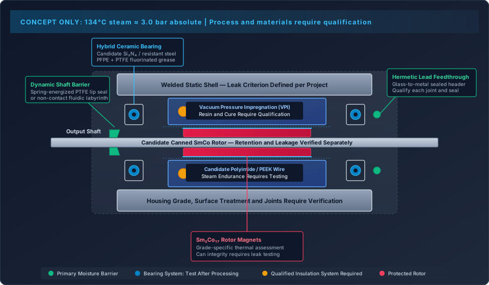
Autoclavable BLDC Motor Design: Steam Sterilization Resistance, Hermetic Sealing, and Bearing Grease Longevity Guide
Autoclavable BLDC motor design guide to steam resistance, hermetic sealing and bearing grease life. Use the checklist to prepare your OEM engineering review.


Axial Flux Motor Air Gap Control Calculator & Guide
Use the axial flux motor air gap control calculator to allocate bending, bearing travel and tolerances. Export your gap budget and submit a project for review.

Axial Flux Motor Cooling: Stator Heat Extraction Guide
Compare stator heat extraction paths for axial flux motor cooling. Evaluate cold plates, jackets, and thermal limits, then submit a project for OEM review.