

Robot Joint Module Thermal Dissipation: Harmonic Drive Heat Trapping, Grease Limits, and Actuator Duty Cycle Budgeting
Plan robot joint module thermal dissipation with grease limits, heat-path checks, and a worked duty-cycle example. Prepare an OEM actuator engineering brief.
1. Executive Summary: Why Integrated Robot Joints Hit a "Thermal Wall"
Robot joint module thermal dissipation must be budgeted against the most restrictive component temperature and the installed heat path. A motor winding insulation class alone cannot establish continuous actuator torque. Request a torque-speed duty profile, the reducer supplier's lubricant limits, and a temperature test using the intended robot link before accepting a continuous rating.
Compact robotic joint actuators can integrate a frameless torque motor, a strain wave (harmonic) gearhead, encoders, a holding brake, and power electronics inside a sealed housing. This architecture concentrates several heat sources behind shared thermal interfaces. Peak torque describes an overload condition; it does not establish how much heat a joint can reject throughout a shift.
Three coupled limits deserve separate checks:
- Winding vs. lubricant limits: Class F (155°C) and Class H (180°C) are insulation thermal classes, not whole-actuator operating setpoints. Grease, seals, magnets, bearings, and electronics each need their own approved limits. There is no universal 70°C–80°C grease ceiling for every strain wave joint.
- Coupled sealed cavity losses: Copper, iron, gear friction, brake coils, and internal drive electronics all contribute heat. Sealing constrains air exchange, so interfaces to the housing and arm link often become important heat paths.
- Thermal expansion and sensor drift: Differential expansion can change bearing preload and encoder alignment. A cool shell or winding reading alone does not establish that every internal component remains within its limit.
Scope: Global OEM robotic joint development, engineering selection, and motion procurement. Reviewed: November 1, 2026. This guide provides screening calculations and RFQ criteria, not measured product ratings or customer case studies. Examples use explicitly assumed inputs. Final limits require supplier approval and installed-assembly bench testing; vacuum applications need separate qualification.
For an active robot design, submit an integrated joint actuator brief detailing torque-speed duty, target ambient temperature, and link geometry. Use the engineering checklist in Section 8 to prepare the specification package.
2. Internal Heat Generation Sources in Sealed Actuator Modules
Quantify each internal heat contributor across the motion profile. Keep motor, gear, brake, and electronics losses separate so that a change in speed or holding strategy does not disappear inside one average efficiency figure.
Figure 1: AI-edited supplier reference showing external housing and flange features. It does not verify internal motor, reducer, encoder configuration, dimensions, or thermal performance.
2.1 Frameless Torque Motor Losses
For balanced three-phase operation, with actual phase RMS current and per-phase resistance:
P_Cu = 3 × I_phase,rms² × R_phase(T)
R_phase(T) ≈ R_phase(20°C) × [1 + 0.00393 × (T − 20°C)]
At an assumed winding temperature of 110°C, the resistance multiplier is 1 + 0.00393 × 90 = 1.3537, about 35% above its 20°C value. Confirm star/delta connection and phase-versus-line quantities before using measured resistance or drive current.
Iron losses depend on electrical frequency, flux density, lamination material, and excitation waveform. For a synchronous motor, f_e = pole_pairs × rpm / 60. Use the motor supplier's loss map at the intended speed and drive settings; a pole count by itself does not determine heating.
2.2 Strain Wave Gearhead Losses
At a nonzero, steady motoring operating point:
P_gear = τ_out × ω_out × (1 − η_gear) / η_gearHere output torque is in Nm, output angular velocity in rad/s, and efficiency is a fraction. Use a supplier map for the selected ratio, torque, speed, lubricant, and temperature; the Harmonic Drive engineering data treats efficiency as condition-dependent (printed pp. 23–24). Do not apply this motoring expression unchanged to backdriving or regenerative operation.
For an illustrative point of 40 Nm at 1 rad/s and an assumed efficiency of 0.80, output power is 40 W and gear loss is 40 × (1 − 0.80) / 0.80 = 10 W. This is arithmetic, not a rating. At stationary holding, mechanical power is zero but motor holding current still produces copper heat; during rotation, include measured no-load gear drag where the efficiency map does not cover it.
2.3 Holding Brake and Auxiliary Electronics Losses
A spring-applied, electrically released holding brake can continue heating during a stationary pause if its coil stays energized. Use its specified holding power or measured voltage and current, including any economizer. Track where regenerative energy goes: into the DC bus, a braking resistor, or drive losses. Electrical braking energy does not automatically become heat in the holding-brake coil.
| Subsystem Component | Loss Mechanism | Required Input | Verification / Budget Boundary |
|---|---|---|---|
| Motor stator coils | Joule loss | Phase current trace and hot phase resistance | Include energized holding periods |
| Motor stator core | Hysteresis and eddy currents | Supplier speed/flux loss map | Include drive waveform conditions |
| Wave generator bearing | Rolling friction and lubricant shear | Input speed and no-load drag data | Do not double-count losses already in a gear map |
| Flexspline tooth mesh | Loaded transmission friction | Torque, speed, ratio, efficiency map | Separate motoring and backdriving |
| Holding brake solenoid | Coil electrical power | Energized time and economized power | A stationary joint may still dissipate heat |
| Encoder and internal drive PCB | Electronics and inverter losses | Measured input minus delivered power | Include only electronics inside the modeled housing |
3. Lumped-Parameter Thermal Resistance Network
Model winding, stator, housing, gear region, and link temperatures as coupled nodes. Calibrate uncertain contact resistances from instrumented tests rather than transferring a resistance value from an unrelated actuator size.
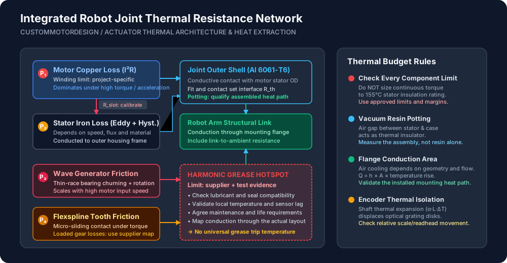
Figure 2: Conceptual heat-path diagram. It supplies no calibrated thermal resistances or certified temperature thresholds; brake and electronics losses must also be added to the project model.
3.1 Five Critical Thermal Barriers
For a single steady-state branch, ΔT = Q_branch × R_th. Use the heat flowing through that branch, not total actuator loss at every internal interface.
- Winding to stator core: Slot insulation, impregnation, voids, and end-turn geometry affect the winding hotspot.
- Stator core to outer housing: Fit, surface contact, and potting may change heat transfer. Determine the assembled interface resistance; resin conductivity alone cannot establish it.
- Rotor to shaft and bearings: Include shaft geometry, bearing contacts, and any motor-to-gear coupling.
- Gear region to mounting flange: Locate gear heat generation and sensor positions for the actual reducer layout. Do not assume the winding is always the hottest node.
- Housing to ambient and robot link: Model air cooling and link conduction separately. A link is not an infinite heat sink; include its temperature rise, adjacent joints, covers, and orientation.
For the restricted case where both external paths terminate at the same fixed ambient temperature:
P_total = P_Cu + P_Fe + P_gear + P_brake + P_electronics
R_external = [1 / R_air + 1 / R_link]⁻¹
T_housing = T_ambient + P_total × R_external
Reproducible screening example: Assume 30 W total loss, 25°C ambient, R_air = 2 K/W, and a complete link-to-ambient path of R_link = 0.5 K/W. The parallel resistance is 0.4 K/W and the estimated housing temperature is 37°C. Removing the link path raises the estimate to 85°C. Neither estimate gives the internal grease or winding hotspot temperature.
For an assumed exposed area of 0.04 m², convection coefficient of 10 W/m²K, and surface rise of 50 K, Q_air = h × A × ΔT = 20 W. These inputs illustrate sensitivity; radiation, shielding, airflow, and mounting alter actual heat rejection.
4. Harmonic Drive Grease Chemistry, Thermal Ceilings, and Failure Modes
Select lubrication for the specific reducer, not from a grease's headline temperature range. Ambient limits, local lubricant temperature, relubrication interval, seal compatibility, speed, and load are different requirements.
4.1 Lubricant Selection and Degradation Boundaries
Elevated temperature changes viscosity and can accelerate oxidation and lubricant aging. Some oil release is part of lubrication behavior; visible bleeding or a dropping-point result alone cannot establish remaining service life. Request the gear manufacturer's temperature/life guidance and approved fill quantity.
The first three rows below transcribe ambient application ranges from Harmonic Drive engineering data, printed p. 16. They are not internal grease trip temperatures or blanket approval for another reducer series.
| Lubricant / Selection Check | Published Ambient Range or Required Evidence | Procurement Decision |
|---|---|---|
| Harmonic Grease SK-1A | 0°C to +40°C ambient | Confirm approval for the selected reducer |
| Harmonic Grease SK-2 | 0°C to +40°C ambient | Confirm series, size, and fill quantity |
| Harmonic Grease 4B No. 2 | −10°C to +70°C ambient | Confirm sealing and application approval |
| Alternative high-temperature grease | Written gear, bearing, and seal compatibility approval | Do not infer actuator rating from grease temperature capability |
| Vacuum or cleanroom lubricant | Environment-specific outgassing, contamination, and life evidence | A PFPE chemistry label is not proof of zero outgassing |
| Local temperature and service interval | Supplier life curve and validated sensor-to-hotspot relationship | Set monitoring and maintenance limits together |
The same catalog relates grease replacement interval to temperature and load (printed p. 17). Its FB component guidance also imposes model-specific duty restrictions (printed p. 110); that restriction must not be generalized to every strain wave actuator. Confirm the current manual revision with the supplier.
4.2 Spatial Gradient: Why Stator Sensors Miss Gearhead Overheating
A winding thermistor measures a local motor temperature. At higher input speeds, gear drag may become more significant; at low-speed holding, copper loss may dominate. There is no fixed temperature offset valid across both operating points.
Place a second sensor near the stationary gear housing or circular-spline mounting region where the design permits. Correlate its reading, lag, and uncertainty with the internal hotspot during prototype testing. Set protection below approved component limits with margins for sensor error and control delay; a housing sensor does not directly measure every grease contact.
5. Duty Cycle Budgeting & Torque Screening
A useful RFQ states torque, speed, acceleration, run/rest durations, brake state, ambient temperature, and link mounting. Duty factor alone cannot establish permissible joint torque.
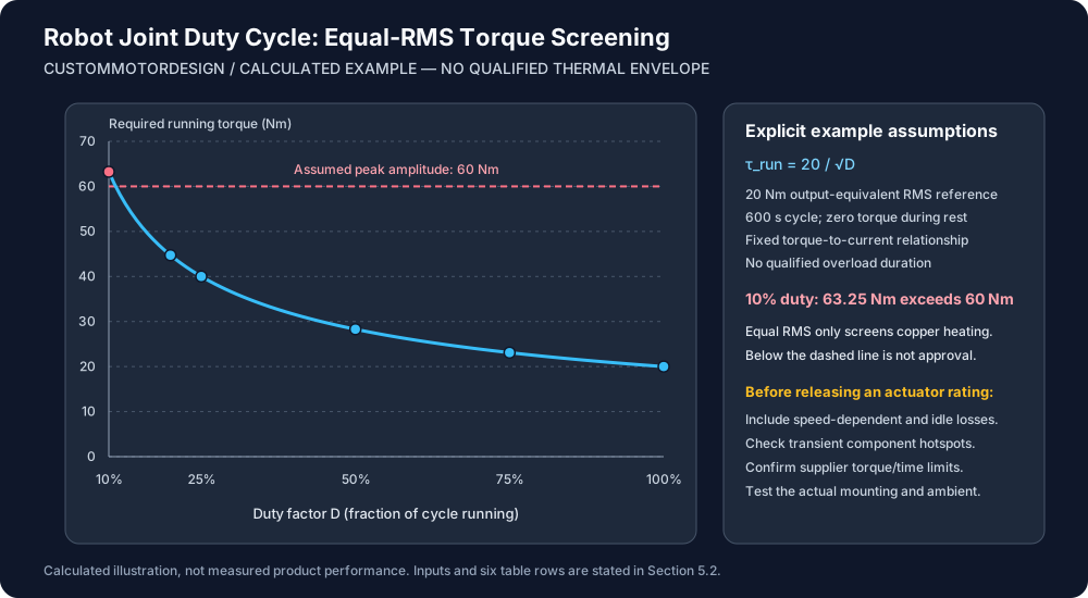
Figure 3: Calculated illustration for the assumptions in Section 5.2. The curve holds an output-equivalent RMS torque at 20 Nm; it does not establish thermal safety, grease temperature, or permitted burst duration.
5.1 Duty Cycle Classifications per IEC 60034-1
Use IEC 60034-1:2026 as the motor rating/performance reference. Its scope does not certify the complete integrated joint.
- S1 (Continuous Running Duty): Constant-load operation long enough to reach thermal equilibrium. State the installed boundary conditions alongside any S1 torque claim.
- S3 (Intermittent Periodic Duty): Repeated constant-load operation and de-energized rest, with starting losses insignificant to heating. State cycle duration as well as duty factor. An energized holding interval is not de-energized rest.
- S5 (Intermittent Periodic Duty with Electric Braking): Includes starting, load operation, electric braking, and rest. Frequent acceleration and braking require their own loss accounting; do not classify a robot trajectory from duty factor alone.
5.2 Reproducible Duty-Cycle Screening Matrix
Assume a 600-second cycle, zero torque during rest, and a fixed ratio/efficiency relationship between output torque and motor current. Hold output-equivalent RMS torque at an arbitrary 20 Nm reference. Compare the required running torque with an assumed 60 Nm peak ceiling, with no qualified burst duration. These are example inputs, not product specifications.
D = t_run / (t_run + t_rest)
τ_equivalent,rms = sqrt[Σ(τ_i² × t_i) / Σ(t_i)]
For zero-torque rest: τ_run = 20 / sqrt(D)| Duty Factor D | Run / Rest in 600 s | Required Running Torque | Equivalent RMS Torque | Comparison with Assumed 60 Nm Peak |
|---|---|---|---|---|
| 100% | 600 s / 0 s | 20.00 Nm | 20.00 Nm | Below amplitude ceiling; continuous rating unverified |
| 75% | 450 s / 150 s | 23.09 Nm | 20.00 Nm | Below amplitude ceiling; duration unverified |
| 50% | 300 s / 300 s | 28.28 Nm | 20.00 Nm | Below amplitude ceiling; duration unverified |
| 25% | 150 s / 450 s | 40.00 Nm | 20.00 Nm | Below amplitude ceiling; duration unverified |
| 20% | 120 s / 480 s | 44.72 Nm | 20.00 Nm | Below amplitude ceiling; duration unverified |
| 10% | 60 s / 540 s | 63.25 Nm | 20.00 Nm | Exceeds assumed peak; reject this combination |
For example, 40 × sqrt(0.25) = 20 Nm. Equal RMS torque only screens average copper heating under the stated current/torque assumptions. Gear losses, iron losses, hot resistance, residual brake heat, thermal capacitance, and transient hotspots can make two equal-RMS cycles thermally different. Even a point below 60 Nm may exceed a supplier's allowed overload duration. Use a transient thermal model and repeated-cycle test before release.
If these operating inputs are not yet defined, request an actuator integration review with the motion trace and mounting section rather than requesting a single peak-Nm quote.
6. Thermal Expansion, Hollow Shaft Elongation, and Dual Encoder Precision
Motor-side feedback supports commutation and velocity control. Output-side feedback can measure output motion after the transmission. For either arrangement, check the sensor's temperature range and the relative movement between scale, readhead, and mounting structure.
6.1 Axial Thermal Elongation Stackup
For a uniform shaft temperature:
ΔL = L_shaft × α_material × (T_shaft − T_assembly)For an assumed 80 mm steel shaft, expansion coefficient of 12 × 10⁻⁶/K, and 55 K rise, ΔL = 80 × 12 × 10⁻⁶ × 55 = 0.0528 mm, or 52.8 µm. If a selected encoder allowed only ±50 µm relative axial movement, this shaft-only estimate would exceed that one-sided allowance. The ±50 µm value is an example, not a typical specification. Include housing and bracket growth, assembly position, and the actual encoder installation limits before predicting signal loss or contact.
6.2 Bearing Preload and Differential Expansion
Different inner-ring, outer-ring, and housing temperatures can change bearing clearance and preload. The direction and magnitude depend on materials, fits, geometry, and constraints. Excess preload may increase friction and heating; insufficient preload can reduce stiffness. Ask the bearing supplier to review the thermal fit stack across the project's declared temperature range, and measure drag and positioning behavior during hot testing.
7. Structural Heat Sinking & Actuator Housing Architecture
The joint housing and mounting flange are part of the installed thermal system. Improving one interface helps only if the downstream arm structure can reject the extra heat.
7.1 Conductive Mounting Flange Interface
Specify contact area, surface condition, fastener preload, and any thermal interface material together. Check bondline thickness, compression, electrical isolation, creep, and serviceability. Flatness or conductivity targets must follow the actual geometry and contact-pressure analysis; one universal drawing tolerance cannot guarantee thermal resistance.
For composite links, use the laminate's directional thermal properties and inserts in the model. If the interface is a bottleneck, evaluate a metallic heat bridge to an exposed structure. There is no fixed carbon-fiber torque penalty applicable to every layup and arm geometry.
7.2 Vacuum Epoxy Potting Qualification
Potting can improve winding-to-housing heat transfer if it replaces a poor heat path. It can also introduce cure stress, differential expansion, trapped voids, and repair constraints. Specify resin thermal performance, dielectric properties, glass transition behavior, cure process, and material compatibility for the actual motor.
Use ASTM D5470-17(2024) as a material/interface thermal measurement reference where applicable. Coupon measurements do not establish the complete assembly's resistance. Qualify the dispensing/vacuum process within the resin supplier's process window, inspect voids, and repeat thermal-cycle and dielectric checks. Do not promise a percentage torque gain from resin conductivity alone.
8. OEM Joint Module Engineering & Procurement Hand-Off Checklist
Before freezing motion limits or requesting formal quotations, use this checklist to agree evidence and acceptance criteria. Unknown values remain open engineering items.
| Verification Item | Engineering Acceptance Criterion | Verification Method / Tool | Status Check |
|---|---|---|---|
| 1. Duty cycle profile | Torque, speed, acceleration, dwell, and brake states declared | Time-series motion trace | [ ] Pass [ ] Review Needed |
| 2. Hot copper resistance | Phase conventions and temperature-dependent resistance included | Motor loss calculation and winding measurement | [ ] Pass [ ] Review Needed |
| 3. Lubricant approval | Reducer-specific grease, fill, temperature, and maintenance limits documented | Current supplier manual and written review | [ ] Pass [ ] Review Needed |
| 4. Sensor placement | Winding and gear-region readings correlated to hotspots with margins | Instrumented prototype and sensor-lag assessment | [ ] Pass [ ] Review Needed |
| 5. Potting qualification | Materials, cure process, void criteria, and dielectric checks agreed | Process record and thermal-cycle qualification | [ ] Pass [ ] Review Needed |
| 6. Installed heat path | Link geometry, interfaces, ambient, orientation, and covers match the rating | CAD review and installed-assembly heat run | [ ] Pass [ ] Review Needed |
| 7. Encoder clearance | Relative thermal growth stays within the selected encoder's installation limits | Full mounting-stack calculation and hot signal check | [ ] Pass [ ] Review Needed |
| 8. Bearing preload | Hot/cold fits and drag meet the selected bearing's requirements | Supplier fit review and drag measurement | [ ] Pass [ ] Review Needed |
| 9. Brake and electronics | Energized idle and braking-energy destinations included | Electrical power measurements and bus-energy review | [ ] Pass [ ] Review Needed |
| 10. Endurance acceptance | Repeat worst-case cycles to stable temperatures; all limits and positioning criteria met | Logged component temperatures, ambient, current, speed, and output load | [ ] Pass [ ] Review Needed |
Agree a test stabilization criterion and observation window in the test plan; do not present an arbitrary temperature-slope threshold as a clause of IEC 60034-1. Repeat at the specified worst ambient and mounting condition. Robot-level positioning evaluation can reference ISO 9283:1998; it does not supply the reducer's lubricant temperature limit.
9. Frequently Asked Questions (FAQ)
Why can't I size a joint module using the motor winding's Class F (155°C) rating?
That thermal class describes insulation, not the allowable temperature of the grease, seals, magnets, bearings, or feedback electronics. Obtain each component limit and validate its hotspot under the intended duty. No single grease failure temperature or service life follows from the winding class.
How much continuous torque improvement does vacuum potting the stator provide?
There is no universal percentage. The gain depends on how much of the total thermal resistance is inside the stator interface and which component limits the assembly. Compare the same motor, housing, duty, ambient, and mounting before and after potting; report measured temperatures and the resulting qualified torque separately.
How do I estimate grease temperature if I can only measure stator winding temperature?
Use a calibrated multi-node thermal model, with validation points across speed, torque, ambient, and mounting conditions. Without that correlation, a winding reading cannot establish grease temperature. Add a gear-region sensor where feasible and account for its offset and lag in protection settings.
What is the effect of mounting a joint module to a carbon fiber robot arm?
The heat path depends on laminate direction, inserts, contact area, and the rest of the arm. Recalculate and test the installed boundary rather than applying a blanket torque reduction. A metallic thermal bridge may help where analysis identifies an interface bottleneck.
Can we use liquid cooling in high-payload collaborative robot joints?
Yes, where the packaging and system design permit it. Specify coolant inlet temperature, flow, pressure drop, leakage controls, condensation protection, and loss-of-flow response. A cooler stator housing does not automatically cool every gear hotspot or authorize continuous operation at a fixed percentage of peak torque.
What causes absolute encoders to lose calibration after extended high-torque cycling?
Possible contributors include relative scale/readhead movement, electronic temperature drift, mounting slip, or a changed mechanical stack. Check hot signal quality and the selected encoder's tolerances before assigning a cause. Thermal isolation can help some layouts but must preserve mounting stiffness and alignment.
10. Authoritative Standards and Technical References
References checked November 1, 2026. Public standards records establish identity and scope; detailed compliance requires the applicable licensed text. The worked examples are this guide's calculations from stated assumptions, not test results supplied by these organizations.
- IEC 60034-1:2026, Edition 15 — Motor rating and performance reference. Its motor scope does not establish a complete joint-module rating.
- Harmonic Drive LLC: FB Component Sets / Engineering Data — Printed pp. 16–17: lubricant selection and replacement; pp. 23–24: efficiency; p. 110: FB-specific lubrication/duty restrictions. Confirm applicability and revision for the purchased reducer.
- ISO 9283:1998 — Industrial robot performance criteria and related test methods; a robot-level reference rather than a lubricant specification.
- ASTM D5470-17(2024) — Thermal impedance and apparent thermal conductivity measurement for thermally conductive electrical insulation materials; not an assembled-actuator torque test.
11. Submit a Project for Integrated Joint Feasibility Review
Bring the operating trace and mounting assumptions into actuator selection before tooling release. CustomMotorDesign's project directions include motor/transmission integration, thermal interface review, and prototype planning; the agreed scope and validation evidence determine the resulting specification.
- Integrated Joint Modules — Review the motor, reducer, feedback, and mechanical interfaces around the joint load case.
- Custom Actuator Integration — Discuss housing, bearings, brake, and sensor packaging constraints.
- Frameless Torque Motors — Review motor-kit and stator integration requirements.
- Custom Engineering Feasibility — Define modeling, prototype, and validation needs for the project.
Submit a Project for Engineering Review with your torque-speed trace, ambient range, envelope, link geometry/material, and known component limits. Identify missing inputs so the team can define the review scope and test plan. Ratings, deliverables, and timing are confirmed for the agreed configuration.
Categories
More Posts

Axial Flux Motor Air Gap Control Calculator & Guide
Use the axial flux motor air gap control calculator to allocate bending, bearing travel and tolerances. Export your gap budget and submit a project for review.


Axial Flux Motor Manufacturing Feasibility
Screen axial flux motor manufacturing feasibility: tooling loads, magnet placement and clearance. Copy the evidence worksheet, then submit a project for review.

Frameless Torque Motor Integration: Rotor Bonding, CTE Mismatch, and Runout Control Guide
Plan frameless torque motor bonding, CTE mismatch and runout control. Use the OEM checklist to compare retention methods and prepare an engineering review.