
First recorded: 2026/10/26
Axial Flux Motor Cooling: Stator Heat Extraction Guide
Compare stator heat extraction paths for axial flux motor cooling. Evaluate cold plates, jackets, and thermal limits, then submit a project for OEM review.
Compare stator cooling paths
Illustrative model for one stator. Edit loss and coolant temperature to see the thermal budget; open the assumptions before using a result.
Preparing interactive controls…
20–10000 W
0–95 °C
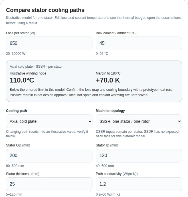
Axial cold plate · SSSR · per stator
Illustrative winding node
110.0°C
Margin to 180°C
+70.0 K
Below the entered limit in this model. Confirm the loss map and cooling boundary with a prototype heat run. Positive margin is not design approval; local hot-spots and coolant warming are unresolved.
Changing path resets h to an illustrative value; verify it below.
DSSR inputs remain per stator. SSDR has no exposed back face for this plate/air model.
80–600 mm
40–500 mm
5–120 mm
0.2–60 W/(m·K)
105–240 °C
5–20000 W/(m²·K)
Input guidance and fixed model assumptions
- Loss per stator: Required. Continuous copper and core losses at the target duty, per stator. Split a DSSR machine total between stators using its loss map.
- Bulk coolant / ambient: Required. Assumed uniform bulk liquid temperature, or ambient for air. Inlet temperature alone omits coolant warming; use the worst local bulk condition.
- Stator OD: Required. Active stator disc outer diameter. These ranges are tool screening bounds, not product ratings.
- Stator ID: Required. Active stator inner diameter; OD minus ID must be at least 15 mm for this simplified model.
- Stator thickness: Required. Thickness of one stator, not the full motor. Used for peripheral conduction and mantle area; axial layer thicknesses remain explicit illustrative assumptions.
- Path conductivity: Required except for direct oil. For axial/air: potting conductivity. For a jacket: effective radial stator conductivity. Obtain directional material or coupon data; these are not interchangeable.
- Project temperature limit: Required. Enter the approved winding limit considering the full insulation system, resin and adjacent components. An insulation class alone is not motor approval.
- Film coefficient h: Required. Enter a measured or correlated coefficient for the actual fluid, temperature and channel geometry. Presets supply illustrative assumptions; flow rate alone cannot establish h.
Axial: 1.8 mm potting + 6 mm iron (k=32) + 0.25 mm TIM (k=2.5), effective convection area 1.8× annulus. Jacket: mean-radius source to OD, 0.2 mm interface (k=1.5). Oil: 40 μm enamel (k=0.22), wetted area 2.8× annulus. Air: 2 mm potting + 6 mm iron, 0.15 mm TIM (k=1.5), fin area 3.5× (annulus + mantle). These fixed assumptions are uncalibrated. Hydraulic losses and current rating are unavailable.
Read reproducible equations and limitations →Total thermal resistance
0.1000 K/W
Loss / one-face annular area
3.23 W/cm²
Resistance breakdown (K/W): conduction 0.0839 · TIM 0.0050 · convection 0.0111. The 20 K low-margin flag is an editorial cue, not a standard.
Load illustrative examples / reset inputs
Same 200/120/25 mm stator, 650 W, 45°C reference. Conductivity is a path-specific hypothesis. No measured performance or universal ranking.
Copy and paste the brief into the project summary; it is not transferred automatically. Unknown parameters are welcome for engineering advice.
1. Decision summary: choose an accessible heat path first
Axial flux motor cooling starts with the surfaces that can actually extract stator heat. An exposed stator back can support a cold plate; a stator between rotors needs a different route. Compare the complete winding-to-fluid resistance before optimizing flow. The tool above explores that decision with explicit, illustrative layer assumptions, not a validated motor rating.
| Decision | Practical conclusion | Evidence and boundary |
|---|---|---|
| Is a stator back accessible? | Consider a stationary axial cold plate for SSSR or the two outside backs of DSSR. | Check the assembly section. The central stator challenge is described in SAE 2026-01-5001; a custom internal cooling channel is a different path. |
| Does a jacket leave a long internal path? | Evaluate directional conductivity and contact resistance before adding pump flow. | This follows the resistance model in section 6; geometry alone does not set a current limit. |
| Can cooling reach the winding directly? | Compare wetting coverage, electrical compatibility, containment and drag. | IEEE's oil-immersion study couples flow and thermal networks; its implementation does not establish a universal oil advantage. |
| Does the calculated margin justify approval? | Use it to identify missing evidence and plan validation. | IEC 60085 concerns thermal classification; it does not validate this calculator or a finished motor. |
These are engineering interpretations of the cited principles. Figures, presets and arithmetic below are conceptual or illustrative; no proprietary thermal measurements are presented.
2. Required inputs and evidence ownership
| Boundary package | Required information | If it is unknown |
|---|---|---|
| Topology | Rotor/stator arrangement, accessible surfaces, active gaps, seals and bearings | Share a section sketch and mark unresolved interfaces. |
| Loss and duty | Copper loss at operating resistance, core loss, continuous duty and transient peaks | Request a loss map; shaft output power is not stator loss. |
| Materials | Directional core/slot conductivity, resin, wire insulation, bondline and contact pressure | Obtain supplier data or test a representative coupon; do not substitute bulk copper conductivity for a winding pack. |
| Manufacturing | Fill/cure method, bondline control, inspection capability, cold-plate joints and leak criteria | Agree a process and acceptance plan before freezing tooling. |
| Cooling and validation | Bulk-fluid temperature, fluid properties, flow distribution, measured/correlated h, pressure drop and sensor positions | Keep a hypothesis explicitly provisional and request a prototype test plan. |
All tool losses, dimensions and cooling surfaces refer to one stator. For DSSR, allocate machine loss to each stator and assess shared-manifold flow and coolant warming separately. Two stators do not automatically halve the thermal resistance of either stator.
3. Topology: SSDR, DSSR and SSSR
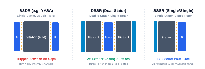
Conceptual Diagram: SSDR central stators face two rotor discs, so this model cannot use an exterior stator back plate. Peripheral, direct-fluid or specifically designed internal channels remain candidates. SSSR and DSSR can expose stator backs; confirm the actual assembly section.
| Topology | Accessible boundary | Candidate path | Unresolved checks |
|---|---|---|---|
| SSDR: one stator between two rotors | Both stator faces face rotating discs | Peripheral conduction, direct fluid, or a specifically designed internal channel | Fluid containment, drag, electrical isolation and stator support |
| DSSR: two stators around one rotor | Each stator can have an outside back interface | One cold plate per accessible stator back | Per-stator loss, unequal flow and manifold routing |
| SSSR: one stator facing one rotor | A back interface can be accessible | Single cold plate or back-mounted finned sink | Axial magnetic force, bearing support and contact area |
SSDR describes rotor/stator count; it does not mean every SSDR is a yokeless segmented machine. The 2025 in-core cooling paper demonstrates a specific segmented-stator channel approach. It broadens the available concepts without making an exterior plate geometrically available.
4. Compare complete heat extraction paths

Conceptual Diagram: Contrasting radial conduction (Path A), axial planar conduction (Path B), and direct dielectric fluid washing (Path C). Accessible interfaces and directional material properties determine the preferred path.
| Path | Heat route | Useful when | Cost or reliability tradeoff |
|---|---|---|---|
| Peripheral jacket | Winding/core → outer stator rim → casing → fluid | Rim conduction and mounting are adequate for the actual loss | Internal conduction can dominate; more flow then has diminishing benefit |
| Axial cold plate | Winding → potting/core → TIM → exposed back plate → fluid | A stationary stator back is available | Bondline, pressure, plate flatness and cooling-channel joins become critical |
| Direct dielectric fluid | Insulated winding surface → fluid film | Wetting and material compatibility can be verified | Fluid handling, seals, drag, contamination and ageing need qualification |
| Forced air on back plate | Winding → back interface → fins → air | Loss and ambient permit sufficient margin | Blower duty, acoustic limits, dust and fouling affect performance |
There is no universal current-density, heat-flux or thermal-resistance range for these labels. Compare the same duty, topology, coolant boundary and evidence level. A sealed tube inside a slot is not equivalent to fluid directly wetting the winding.
5. Direct oil: heat removal and rotating-disc drag
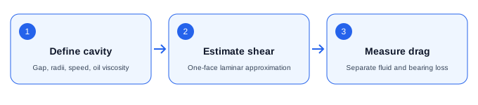
Conceptual Diagram: A simple laminar shear estimate describes one wetted annular face only. Rotor-stator cavity flow depends on clearance, rotation, through-flow and viscosity. Cylindrical Taylor-Couette transition thresholds do not classify this disc cavity.
For a narrow, fully wetted annular gap, a deliberately simplified laminar shear approximation is:
u(z) = omega × r × z / g
shear stress = mu × omega × r / g
P_one_face = pi × mu × omega² × (r_outer⁴ − r_inner⁴) / (2 × g)
This expression follows by integrating local shear power over one face. Two identical wetted faces double it. It assumes Newtonian fluid, a linear velocity profile and negligible secondary flow; it is not a high-speed drag prediction.
Rotor-stator disc cavities have their own secondary flow and transition behavior, as discussed by Launder, Poncet and Serre. Applying cylindrical Taylor-Couette thresholds to an axial disc gap is not justified. Neither a universal rim-speed cutoff nor a fixed multi-kW penalty is established here.
Compare flooded, targeted/scavenged and isolated-channel concepts using the actual viscosity-temperature curve, gap, speed and torque measurements. A dry-gap barrier adds thermal and mechanical constraints. Carbon-fiber composite can conduct electricity; any barrier material needs dielectric, chemical, stiffness and loss qualification for its specific formulation.
6. Reproducible model assumptions and equations
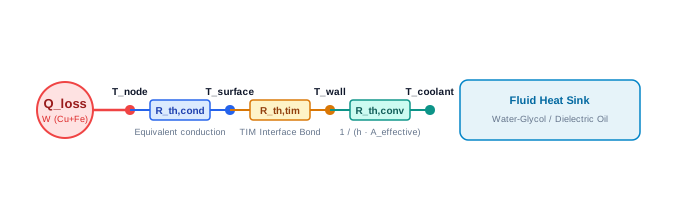
Conceptual Diagram: Illustrative single-node resistance network for conduction, interface and fluid-film terms. Its fixed layers and effective areas are listed in section 6. It does not resolve a local winding hot-spot or the detailed slot insulation path.
The tool is a steady resistance network with a single winding node and fixed bulk-fluid reference. With dimensions in metres:
A = pi / 4 × (OD² − ID²)       [one-face annular area]
M = pi × OD × thickness        [outer mantle area]
R_total = R_conduction + R_TIM + R_convection
T_node = T_bulk + loss_per_stator × R_total
Margin = entered_project_limit − T_node| Path | Conduction resistance (K/W) | Interface resistance (K/W) | Convection resistance (K/W) |
|---|---|---|---|
| Axial cold plate | 0.0018/(k × A) + 0.006/(32 × A) | 0.00025/(2.5 × A) | 1/(h × 1.8 × A) |
| Peripheral jacket | ln[OD / ((OD+ID)/2)]/(2 × pi × k × thickness) | 0.0002/(1.5 × M) | 1/(h × M) |
| Direct oil | 0.00004/(0.22 × 2.8 × A) | 0 | 1/(h × 2.8 × A) |
| Forced air on back plate | 0.002/(k × A) + 0.006/(32 × A) | 0.00015/(1.5 × A) | 1/[h × 3.5 × (A+M)] |
Every layer thickness, fixed conductivity and area multiplier in this table is an illustrative assumption, not measured product data. The jacket uses an equivalent source at the mean annular diameter; it does not solve distributed heat generation. The axial and air models use fixed layer thicknesses rather than deriving them from the entered stator thickness. In the tool, k is potting conductivity for axial/air and effective radial stator conductivity for the jacket; it is unused for direct oil. These meanings require different evidence.
The entered h must represent the actual film and wetted surface. Switching path loads an illustrative h: plate 2500, jacket 1900, oil 3100, air 48 W/(m²·K). Verify it or replace it. Flow alone cannot determine h without geometry and fluid properties. Area multipliers also need calibration before project use.
The network omits detailed slot insulation, spreading/contact variations, coolant warming, rotor/magnet temperatures, churning heat and transient storage. The zero TIM term for oil does not remove wire enamel or all internal winding resistance. A positive margin is not a hot-spot or life qualification. Below 20 K triggers an editorial low-margin cue, not a standard-mandated reserve. Very high extrapolated temperatures indicate an inadequate assumed heat budget; constant properties cannot predict the actual temperature after material degradation.
7. Cold-plate channels: compare matched operating points
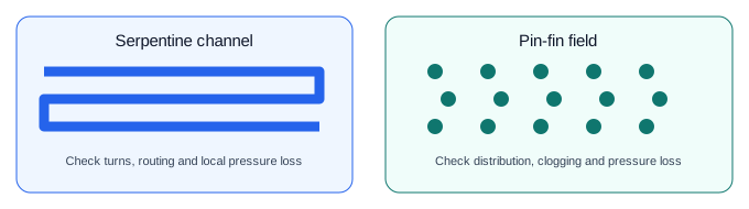
Conceptual Diagram: Conceptual layouts only. Channel geometry changes flow distribution, heat transfer and pressure drop. Velocity alone does not establish Reynolds number or an erosion limit; use the selected fluid, hydraulic diameter, alloy and supplier limits.
| Concept | What to evaluate | Evidence before selection |
|---|---|---|
| Serpentine or spiral passage | Routing, bends, local wall temperature and outlet warming | Conjugate heat-transfer analysis and a pressure/flow curve |
| Parallel channels | Flow balance, inlet distribution and blockage sensitivity | Per-branch flow or temperature evidence |
| Pin-fin field | Local mixing, bypass, cleanability and pressure loss | Correlation valid for the actual geometry, then a prototype |
| Embedded isolated tube | Contact, bend radius, dielectric separation and joint accessibility | Thermal contact, leak and electrical tests |
Velocity is not a stand-alone flow-regime or corrosion criterion. Reynolds number is Re = density × velocity × hydraulic_diameter / viscosity; fluid temperature and channel size matter. No universal 0.8–2.0 m/s window or 2.5 m/s erosion threshold is asserted. Set alloy, inhibitor, cleanliness and velocity limits with the selected coolant and cold-plate suppliers. Select heat-transfer correlations only within their documented geometry and flow regime.
8. Materials: what is known and what is missing
| Property | Tool treatment | Project evidence needed |
|---|---|---|
| Potting conductivity | User hypothesis for axial/air | Resin grade, temperature, cure, direction and coupon test |
| Effective radial stator conductivity | User hypothesis for a jacket | Representative composite winding/core measurement or validated model |
| Enamel / back-iron / TIM | Fixed assumptions in section 6 | Actual thicknesses, directional properties and interface pressure |
| Fluid properties and h | User-supplied h; viscosity/heat capacity not modeled | Fluid grade, concentration, ageing and temperature-dependent data |
| Project temperature limit | User-supplied comparison limit | Approved system limit including insulation, adhesive, magnets, sensors and required life |
Copper fill factor changes geometry, insulation paths and losses; it cannot determine an isotropic slot conductivity or a percentage hot-spot improvement by itself. IEC 60085:2007 distinguishes thermal evaluation of materials and systems. A class number does not establish the finished motor's permissible winding temperature at every duty and life requirement.
9. Encapsulation, void inspection and TIM ageing
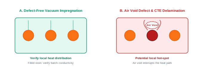
Conceptual Diagram: Air voids can interrupt heat transfer; the resulting temperature rise depends on void geometry and local loss. Mismatched CTE can trigger adhesive delamination during rapid thermal cycling.
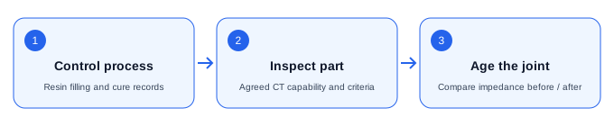
Conceptual Diagram: A supplier-approved impregnation or potting process needs its own pressure, cure and inspection plan. CT acceptance limits are agreed for the part; ASTM E1570 does not supply a universal void fraction. ASTM D5470 characterizes steady-state impedance; endurance cycling needs a separate protocol.
Air voids and delamination can interrupt the intended heat path. Their location, size and local heat generation matter; a fixed temperature penalty cannot be assigned to every defect. Choose impregnation, casting or another fill process with the resin supplier and manufacturing team, then establish a qualified cure and inspection plan.
ASTM E1570-19(2026) addresses fan-beam CT examination. CT resolution and acceptance criteria must be agreed for the actual part; there is no universal 1% void fraction or 0.5 mm void limit supplied by that practice. ASTM D5470-17(2024) characterizes steady-state thermal impedance. It does not prescribe a 1000-cycle pump-out test or guarantee a particular material's life. Define thermal cycling separately, and compare representative joint impedance before and after ageing.
10. Hydraulic power and system efficiency
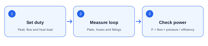
Conceptual Diagram: A decision workflow, not measured curves. Compare heat transfer and complete-loop pressure drop at the same fluid temperature and flow. No universal optimum or channel-size power law is assumed.
DeltaP = f × (length / hydraulic_diameter) × density × velocity² / 2
P_pump_electrical = volume_flow × total_loop_DeltaP / pump_efficiency
Pressure losses in fittings, manifolds and hoses add to the plate loss. Channel-size scaling depends on what is held constant, geometry and friction factor; it is not universally proportional to inverse diameter cubed.
Illustrative arithmetic: 12 L/min is 0.0002 m³/s. At 1.5 bar total loop drop and 50% pump efficiency, electrical pumping power is 0.0002 × 150000 / 0.5 = 60 W. That does not establish a cold-plate pressure drop or pump efficiency for any motor. Include blower/pump, churning and drive losses within the agreed system-efficiency boundary. The tool does not predict hydraulic pressure or auxiliary power.
11. Three worked scenarios you can reproduce
Use the presets above. All share OD 200 mm, ID 120 mm, one-stator thickness 25 mm, 650 W per stator, bulk reference 45°C and project limit 180°C. k=1.2 W/(m·K) is an illustrative, path-specific hypothesis for plate/jacket; oil bypasses it. All other layer/area assumptions are in section 6. These are hypothetical alternatives, not measurements of the same interchangeable motor assembly.
| Metric | Axial plate example | Peripheral jacket example | Direct oil example |
|---|---|---|---|
| Topology | SSSR | SSDR | SSDR |
| Assumed h, W/(m²·K) | 2500 | 1900 | 3100 |
| Conduction R, K/W | 0.0839 | 1.1838 | 0.0032 |
| TIM R, K/W | 0.0050 | 0.0085 | 0 |
| Convection R, K/W | 0.0111 | 0.0335 | 0.0057 |
| Total R, K/W | 0.1000 | 1.2258 | 0.0090 |
| Linear winding-node result, °C | 110.0 | 841.8 — outside material validity | 50.8 |
| Margin to entered limit, K | +70.0 | −661.8 — failed budget | +129.2 |
| Decision | Validate accessible back interface | Revise assumed conduction path or loss | Validate wetting, fluid compatibility and drag |
Scenario A — exposed back: For the axial example, conduction contributes about 84% of total resistance. Doubling h from 2500 to 5000 reduces total R to 0.0944 K/W and the winding node to 106.4°C. Under these assumptions, improving internal layers matters more than adding flow.
Scenario B — rim cooling: The jacket example is dominated by its assumed effective radial conductivity. Its 841.8°C linear extrapolation is a failed heat-budget flag, not an attainable continuous operating temperature or a prediction of a specific motor. Obtain directional material evidence, reduce loss or redesign the path before spending on pump capacity.
Scenario C — direct fluid: The model's lower node temperature depends on 2.8× annular wetted area and assumed h, with no coolant warming, drag heat or detailed internal slot gradient. The actionable next step is a coverage/flow/drag and compatibility test; the number does not establish a higher current rating.
12. Risk, cost and scenario fit
| Risk | Decision impact | Mitigation or alternative |
|---|---|---|
| Treating shaft power as stator loss | Invalid heat budget | Obtain a loss map at temperature and target duty |
| Selecting an inaccessible plate interface | Assembly cannot realize the model | Review the section drawing; assess rim or internal fluid paths |
| Uncontrolled voids or bondline | Unit-to-unit thermal variation | Qualify process, inspection capability and representative joints |
| Coolant incompatibility or leakage | Electrical and mechanical reliability risk | Age material coupons, verify dielectric properties and leak-test assembled parts |
| Pump, seals or channels exceed cost budget | A cooler winding can still worsen system economics | Compare complete loop cost, auxiliary power, service access and passive alternatives |
| Air-cooled design exposed to fouling | Loss of margin over service life | Validate worst ambient and blocked/fouled airflow; consider sealed conduction cooling |
| Continuous model applied to pulse duty | Peak hot-spots remain unknown | Use transient thermal analysis with measured time constants |
13. Prototype validation and sensor placement
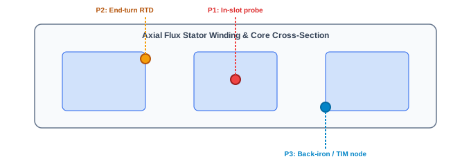
Conceptual Diagram: Validation sensor architecture: Electrically isolated probes can reduce electrical measurement interference; installation, isolation and calibration still require qualification. RTDs track end turns and coolant temperatures.
Locate sensors using predicted hot regions and record coordinates, calibration and measurement uncertainty. Compare winding probes with resistance-derived average temperature where suitable; they measure different quantities. Electrically isolated probes can reduce interference, but sensor installation does not remove insulation or isolation qualification.
Use a controlled heat run to identify the conductive path, then run the actual drive and torque-speed duty to include frequency-dependent losses. Agree steady-state criteria, transient limits and test abort conditions before the run. Log coolant inlet/outlet temperature, flow and pressure with the motor measurements. Where the heat balance is applicable, use heat_to_fluid = mass_flow × heat_capacity × (T_out − T_in) and account for heat leaving other boundaries.
Do not select overload pulse amplitudes or an equilibrium criterion from a generic blog. IEC 60034-1:2026 covers applicable machine ratings and performance; rail and road vehicle machines are excluded from its stated scope and require the appropriate standards and project specifications.
14. OEM engineering handoff
Prepare the topology section, target torque-speed duty, voltage, stator loss map, package envelope, material uncertainties, cooling infrastructure, intended environment and validation objectives. Include prototype quantities and annual volume as planning inputs. Unknown values are acceptable; identify them instead of inventing precision.
Use Copy engineering brief, then paste the text into the summary on Submit a Project. Clipboard failure exposes selectable text. The link does not automatically transfer the brief. Exchange confidential drawings through an agreed channel after confidentiality requirements are settled.
Relevant live capabilities: Special Motor Topologies, Custom Engineering, Stator & Rotor Design, and Testing & Production.
15. Decision FAQ
Architecture and usable boundaries
When can a peripheral jacket be sufficient?↓
When the complete winding-to-rim path and casing interface can remove the actual stator loss within the approved temperature budget. Disc aspect ratio alone does not establish a current limit. Obtain effective directional conductivity and a representative heat run.
How do SSDR, DSSR and SSSR change cooling access?↓
SSDR places one stator between two rotors, so an exterior stator back plate is unavailable in this model. SSSR can expose one stator back; DSSR can expose a back on each of its two stators. Confirm the actual assembly section and any internal cooling channels.
Why is the loss input per stator for DSSR?↓
Each stator has its own loss and heat path. Allocate machine loss between stators before entering it. Identical stators at the same per-stator loss do not gain half the thermal resistance simply because there are two stators; shared flow and coolant warming also need assessment.
Can this tool calculate continuous current density?↓
No. Conductor area, winding resistance at temperature, turns, AC loss and a validated thermal model are missing. The tool reports an illustrative thermal budget only. Request a winding loss map and prototype validation before assigning a current rating.
Can forced air meet continuous duty?↓
It can if the actual loss, ambient conditions, accessible heat path, fin area and airflow maintain the required thermal budget. This tool models air on an accessible stator back plate and rejects that path for SSDR. Check blower duty, dust, noise and fouling.
Fluid cooling and hydraulic tradeoffs
What does the film coefficient h input represent?↓
It is the heat-transfer coefficient for the actual fluid film and wetted surface. Derive it from a suitable correlation or measurement. Changing the cooling path loads an illustrative default, which must be verified. Flow rate alone cannot establish h without channel geometry and fluid properties.
Does direct oil always outperform a cold plate?↓
No. The illustrative oil result depends on assumed wetted area and h, while detailed winding gradients, coolant warming and rotor drag are omitted. Verify wetting coverage, material compatibility, electrical properties, sealing and parasitic losses before choosing direct fluid.
Can cylindrical Taylor-Couette thresholds classify an axial disc gap?↓
No. A rotating-disc cavity has different flow geometry and secondary circulation. The one-face laminar shear estimate in the guide is limited to its stated assumptions; transition and drag need a suitable rotor-stator model and test evidence.
Is there a universal coolant velocity limit for aluminum cold plates?↓
No universal limit is established here. Reynolds number also depends on hydraulic diameter and viscosity; corrosion and erosion depend on alloy, chemistry, temperature and geometry. Agree velocity, inhibitor, cleanliness and inspection requirements with the selected suppliers.
How should pump power be evaluated?↓
Use electrical pump power equal to volume flow times total loop pressure drop divided by pump efficiency, with consistent SI units. Include hoses, manifolds and fittings. The tool cannot predict pressure drop or pump efficiency from its inputs.
Materials and manufacturing evidence
How should path conductivity be chosen?↓
For axial and air paths, enter the potting conductivity at the relevant temperature and cure condition. For the jacket, enter an effective radial stator conductivity supported by a composite measurement or validated model. These are different properties. Direct oil bypasses this parameter in the simplified network.
Does ASTM E1570 set a maximum void fraction?↓
No. It is a CT examination practice, not a universal stator acceptance specification. Agree defect size, location, detection capability and acceptance criteria for the actual assembly. A percentage limit or scan resolution needs its own project evidence.
Does ASTM D5470 prescribe a thermal cycling life test?↓
No. It characterizes steady-state thermal impedance. Define a separate application-specific ageing and cycling protocol, then compare representative joint impedance before and after exposure. The standard does not guarantee pump-out resistance.
Does copper fill factor determine winding thermal conductivity?↓
No. Conductor arrangement, insulation, resin, interfaces and direction affect the effective conductivity as well as the loss distribution. A fill percentage alone cannot establish a conductivity or a fixed hot-spot reduction.
Interpretation, validation and handoff
Does a positive model margin mean the motor is safe?↓
No. It is the difference between an entered project limit and an illustrative winding node, not a measured local hot-spot. The 20 K low-margin cue is editorial, not a standard. Check actual insulation-system, adhesive, magnet, sensor and service-life limits.
Can the tool replace CFD, FEA or prototype heat runs?↓
No. Fixed layers, area factors and a uniform bulk-fluid reference are uncalibrated assumptions. Use appropriate spatial and transient models, then representative heat runs and a measured loss map to validate the design.
What if an input or cooling path is unavailable?↓
Correct the marked inputs or load an illustrative example to reset. An SSDR exterior back-plate result is withheld; choose a peripheral or direct-fluid path to explore alternatives, or submit known boundaries and request advice on a custom cooling channel.
How do I submit the screening brief?↓
Copy the brief and paste it into the project summary on Submit a Project; the link does not transfer it automatically. If clipboard access fails, manually select the displayed text. Include duty, envelope, topology, cooling infrastructure and unknowns for engineering review.
16. Sources, dates and evidence limits
Prepared by the CustomMotorDesign Engineering Team. First recorded in the repository: 26 October 2026. Last technical review: 26 October 2026. Publisher abstracts and public standard descriptions establish the scope below; they do not imply access to all paid clauses or certify a design.
| Primary source | What it supports here | Limit |
|---|---|---|
| IEC 60034-1:2026, edition 15 | Current rating/performance reference, replacing 2022 edition | Apply its scope and the project's applicable standards; no approval of this tool |
| IEC 60085:2007 | Thermal classification of insulation materials and systems | No universal finished-motor operating limit inferred |
| ASTM D5470-17(2024) | Steady-state thermal impedance characterization | Not an endurance-cycling protocol |
| ASTM E1570-19(2026) | CT examination practice | Acceptance and detection capability need project agreement |
| Yao et al., SAE 2026-01-5001 | Central-stator cooling challenge and a design-specific cooling investigation | Its implementation/results are not generalized to other motors |
| In-Core Cooling for YASA Machines, IEEE, online 2024; issue 2025 | Internal-channel concept evaluated through models and a motorette experiment | Different from a universal production motor rating |
| Oil-immersed flow/thermal network, IEEE, online 2025; issue 2026 | Flow coverage, coupled modeling and design-specific experimental validation | Does not calibrate our illustrative area or h assumptions |
| Launder, Poncet & Serre, 2010 | Rotating-disc cavity flow complexity | No universal disc transition cutoff asserted |
The tool's coefficients, area factors, example material values and 20 K warning cue remain illustrative. Public evidence does not establish universal continuous-current limits, erosion velocity thresholds, defect temperature penalties or pump-out degradation percentages. Those claims are deliberately excluded from the decision workflow.
17. Request a project-specific thermal review
Submit a Project with your known boundaries and copied screening brief. Request assessment of the accessible heat path, loss assumptions, material evidence and prototype validation plan. Cooling architecture and any performance or schedule commitments require project-specific review.